3.9 Main Frequency Reference
u
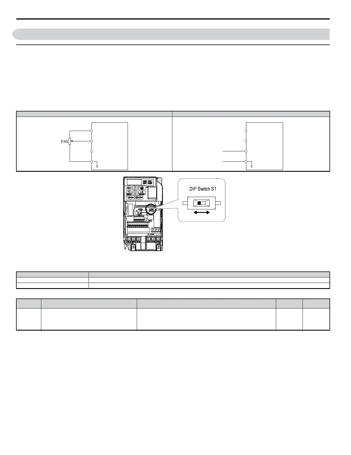
Terminal A2 Switch
The main frequency reference can either be a voltage or current signal input. For voltage signals both analog inputs, A1 and A2, can be used, for current
signals A2 must be used.
To use current input at terminal A2, set the DIP switch S1 to "I" (factory setting) and set parameter H3-09 = “2” or “3” (4-20 mA or 0-20 mA). Set
parameter H3-10 = “0” (frequency reference).
Note: If Terminals A1 and A2 are both set for frequency reference (H3-02 = 0 and H3-10 = 0), the addition of both input values builds the frequency reference.
When using input A2 as voltage input, set the DIP switch S1 to “V” (left position) and program parameter H3-09 to “0” (0 to +10 Vdc with lower limit)
or “1” (0 to +10 Vdc without lower limit).
Table 3.12 Frequency Reference Configurations
Voltage Input Current Input
Drive
Main speed
frequency reference
(voltage input)
Main speed
frequency reference
(current input)
Frequency reference
common
+10.5 V
20 mA current
0 to 10 V
+V
A1
A2
AC
Drive
Main speed
frequency reference
(voltage input)
Main speed
frequency reference
(current input)
Frequency reference
common
4 to 20 mA input
or
0 to 20 mA input
+10.5 V
20 mA current
+V
A1
A2
AC
V I
Figure 3.28 DIP Switch S1
Table 3.13 DIP Switch S1 Settings
Setting Value Description
V (left position) Voltage input (0 to 10 V)
I (right position) Current input (4 to 20 mA or 0 to 20 mA): factory setting
Table 3.14 Parameter H3-09 Details
No. Parameter Name Description
Setting
Range
Default
Setting
H3-09
Frequency ref. (current)
terminal A2 signal level selection
Selects the signal level for terminal A2.
0: 0 to +10 V, unipolar input (negative frequency reference values are zeroed)
1: 0 to +10 V, bipolar input (negative frequency reference changes the direction)
2: 4 to 20 mA
3: 0 to 20 mA
0 to 3 2
3.9 Main Frequency Reference
50
YASKAWA ELECTRIC SIEP C710606 18A YASKAWA AC Drive – V1000 Technical Manual (Preliminary)

 Loading...


