EasyManuals Logo

YASKAWA V1000 Series Technical Manual

YASKAWA V1000 Series
372 pages
To Next Page IconTo Next Page
To Previous Page IconTo Previous Page
Page #51 background imageLoading...
Page #51 background image
3.10 MEMOBUS/Modbus Termination
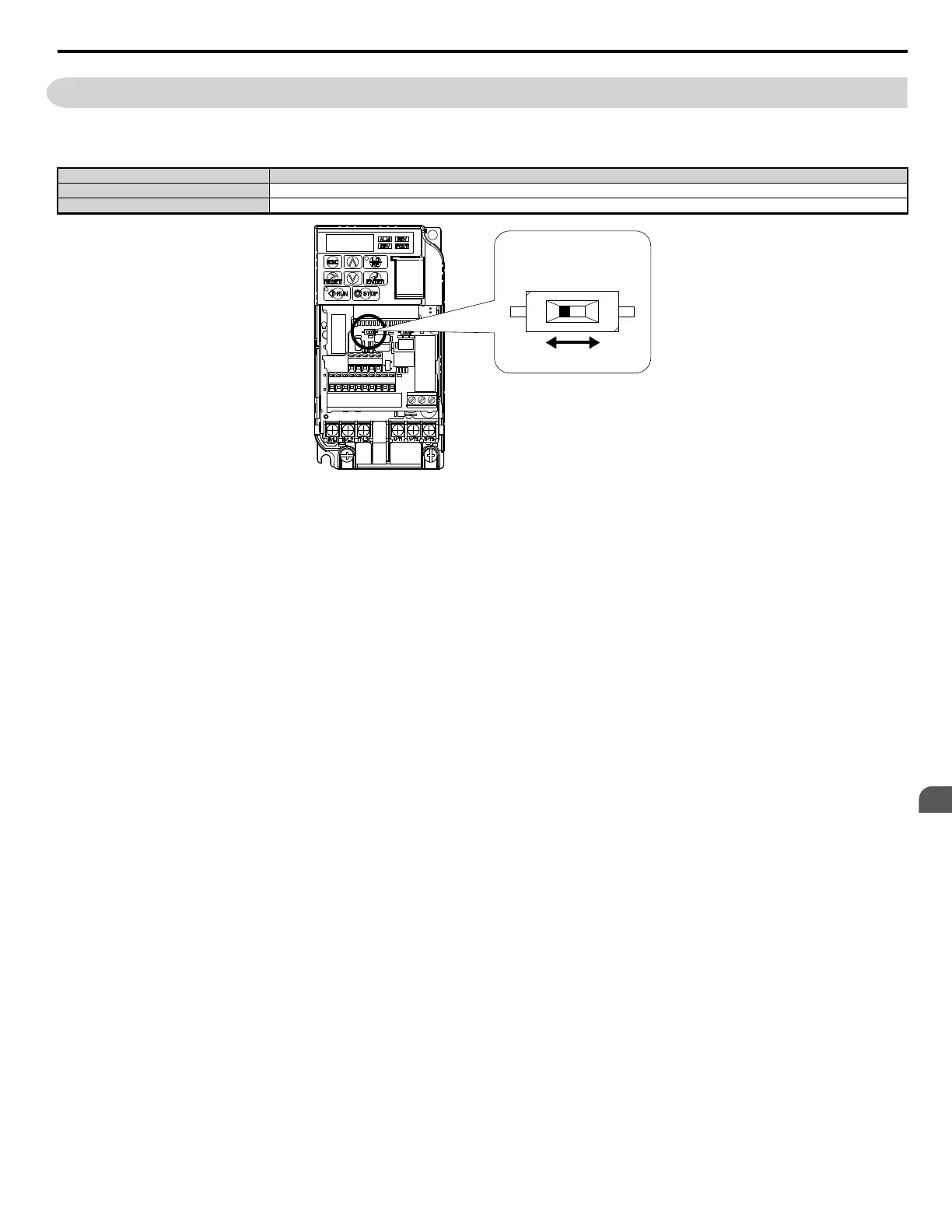
DIP switch S2 controls the terminal resistance as shown in the
Figure 3.29 . The OFF position is the default of the terminating resistor switch for
MEMOBUS/Modbus communications. Turn the terminal resistor switch ON when the drive is the last drive in a series of slave drives.
Table 3.15 MEMOBUS/Modbus Switch Settings
S2 Position Description
ON Internal terminal resistance ON
OFF Internal terminal resistance OFF (no terminal resistance); default setting
OFF ON
DIP Switch S2
Figure 3.29 DIP Switch S2
Note: Refer to the MEMOBUS/Modbus communications manual for details on MEMOBUS/Modbus.
3.10 MEMOBUS/Modbus Termination
YASKAWA ELECTRIC SIEP C710606 18A YASKAWA AC Drive – V1000 Technical Manual (Preliminary)
51
3
Electrical Installation

Table of Contents

Other manuals for YASKAWA V1000 Series

Questions and Answers:

Question and Answer IconNeed help?

Do you have a question about the YASKAWA V1000 Series and is the answer not in the manual?

YASKAWA V1000 Series Specifications

General IconGeneral
ModelV1000 Series
SeriesV1000
Output Frequency0.1 to 400 Hz
Overload Capacity150% for 60 seconds
TypeAC Drive
Control MethodV/f Control
Input Voltage200-240V, 380-480V
Output Voltage0 to Input Voltage
Power Range0.1 to 18.5 kW
Horsepower0.2 to 25 HP
Protection FeaturesOvercurrent, Overvoltage, Undervoltage, Overheating, Short Circuit, Ground Fault
Communication InterfacesModbus RTU
EnclosureIP20
Ambient Temperature-10 to +50°C
Storage Temperature-20 to +60°C
Humidity5 to 95% RH (non-condensing)
Cooling MethodFan Cooled

Related product manuals