5.5 E: Motor Parameters
E parameters cover motor related settings.
u
E1: V/f Characteristics
n
E1-01: Input Voltage Setting
Set the input voltage parameter to the nominal voltage of the connected AC power supply. This parameter adjusts the levels of some protective features
of the drive (i.e., overvoltage, Stall Prevention, etc.).
No. Parameter Name Setting Range Default
E1-01 Input Voltage Setting 155 to 255 200 V
Note: The setting range shown here is for 200 V class drives. Double this value when working with 400 V class units.
NOTICE: Set parameter E1-01 to match the input voltage of the drive. Drive input voltage (not motor voltage) must be set in E1-01 for the protective features of the drive to function
properly. Failure to comply could result in improper drive operation.
Detailed Description
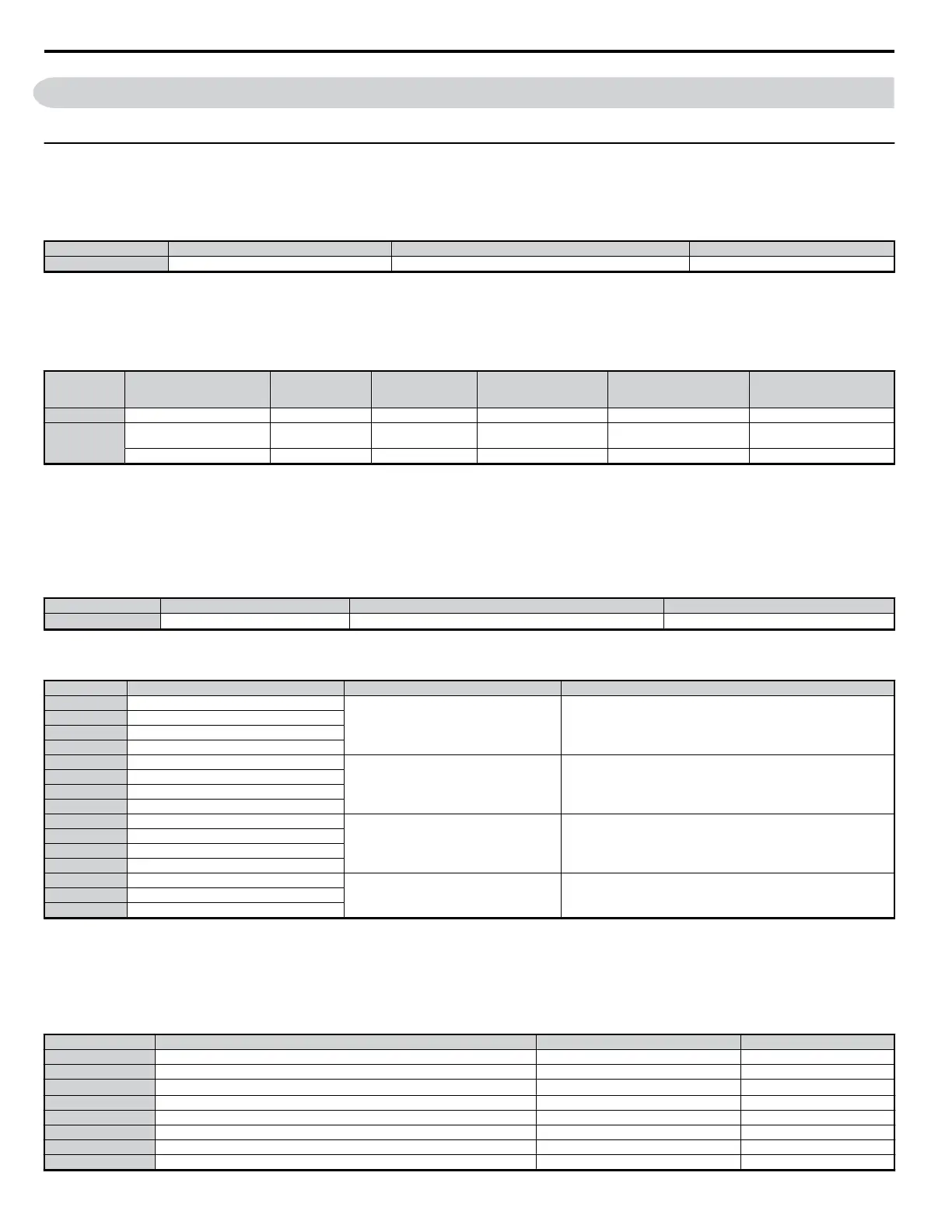
The input voltage level determines the overvoltage detection level and the operation level of the braking transistor as shown in the table below.
Voltage Setting Value of E1-01
OV Detection Level
(approx.)
BTR Operation
Level (approx.)
UV Detection Level
(L2-05)
Desired DC Bus Voltage
during KEB (L2-11)
Voltage Level for OV
Suppression, Stall
Prevention (L2-17)
200 V Class all settings 410 V 394 V 190 V (single phase = 160 V) 240 V 370 V
400 V Class
setting greater than or equal to
400 V
820 V 788 V 380 V 480 V 740 V
setting < 400 V 740 V 708 V 350 V 440 V 660 V
Note: This data is for an internal dynamic braking resistor of 0.1 to 18.5 kW. For larger units, see “Dynamic Braking Resistor Unit for VARISPEED-600 Series, TOBPC720600000”
n
E1-03: V/f Pattern Selection
n
E1-04 to E1-13
This parameter is only available when using V/f Control. It allows the user to set the V/f pattern and drive input voltage as needed. When running a high-
speed or other type of special-purpose motor, this function can be used to fine-tune the amount of torque needed for the load.
No. Parameter Name Setting Range Default
E1-03 V/f Pattern Selection 0 to F
F (user-set)
*
*This parameter is not reset when the drive is initialized with A1-03.
Table 5.4 V/f Pattern
Setting Specification Characteristic Application
0 50 Hz
Constant torque
For general purpose applications. Torque remains constant regardless of
changes to speed.
1 (F) 60 Hz
2 60 Hz (with 50 Hz base)
3 72 Hz (with 60 Hz base)
4 50 Hz, Heavy Duty 2
Derated torque
For fans, pumps, and other applications that require torque derating relative
to the load.
5 50 Hz, Heavy Duty 1
6 50 Hz, Heavy Duty 1
7 50 Hz, Heavy Duty 2
8 50 Hz, mid starting torque
High starting torque
Select high starting torque when:
Wiring between the drive and motor exceeds 150 m
A large amount of starting torque is required
AC Reactor is installed
The motor exceeds the largest recommended motor for the drive.
9 50 Hz, high starting torque
A 60 Hz, mid starting torque
B 60 Hz, high starting torque
C 90 Hz (with 60 Hz base)
Constant output
When operating at greater than 60 Hz. This requires that constant voltage be
application.
D 120 Hz (with 60 Hz base)
E 180 Hz (with 60 Hz base)
Detailed Description
The drive operates utilizing a set V/f pattern to determine the appropriate output voltage level for each commanded speed. There are 15 different preset
V/f patterns to select from with varying voltage profiles, saturation levels (frequency at which maximum voltage is reached), and maximum frequencies.
There are also settings for custom V/f patterns that will allow the programmer to manually set the V/f pattern using parameters E1-04 through E1-10.
Using parameter E1-03, the programmer can select one of the preset V/f patterns or chose between a custom V/f pattern with an upper voltage limit (E1-03
= “F: Custom V/f”).
No. Name Setting Range Default
E1-04 Max Output Frequency (FMAX) 40.0 to 400.0 *2, *3, *4
E1-05 Max Voltage (VMAX) 0.0 to 255.0*1 *2, *3, *4
E1-06 Bass Frequency (FA)
0.0 to 400.0
*2, *3, *4
E1-07 Mid Output Frequency (FB) 0.0 to 400.0 *2, *3
E1-08 Mid Output Frequency Voltage (VC) 0.0 to 255.0 *1 *2, *3
E1-09 Minimum Output Frequency (FMIN) 0.0 to 400.0 *2, *3, *4
E1-10 Minimum Output Frequency Voltage (VMIN) 0.0 to 255.0 *1 *2, *3
E1-11 Mid Output Frequency 2 0.0 to 400.0 0.0 Hz
5.5 E: Motor Parameters
146
YASKAWA ELECTRIC SIEP C710606 18A YASKAWA AC Drive – V1000 Technical Manual (Preliminary)

 Loading...


