No. Name Setting Range Default
E1-12 Mid Output Frequency Voltage 2
0.0 to 255.0
*1
0.0 V
E1-13 Base Voltage (VBASE) 0.0 to 255.0 *1 0.0 V
*1. Values shown here are for 200 V class drives. Double the value when using a 400 V class unit.
*2. Default setting is determined by the control mode (value shown here is for V/f Control).
*3. Default setting varies based on the V/f pattern set to E1-03.
*4. When using PM Open Loop Vector, the default setting is determined by the motor code set to E5-01.
Setting Instructions
1. Set the input voltage for the drive. For instructions, see page 133.
2. Choose one of the two following V/f patterns:
Select one of the 15 preset V/f patterns (setting = 0 through E)
Custom V/f pattern (setting = F)
3. When using one of the preset patterns, the parameters listed below are set automatically.
When using a custom V/f pattern, set these parameters as desired:
E1-04 (Max Output Frequency), E1-05 (Max Voltage), E1-06 (Base Frequency), E1-07 (Mid Output Frequency, E1-08 (Mid Output Frequency Voltage),
E1-09 (Min Output Frequency), E1-10 (Min Output Frequency Voltage)
4. Settings for the E1 parameters are determined by drive capacity. Drive capacities are divided into the two following ranges:
V/f pattern for 0.1 to 3.7 kW drives
V/f pattern for 5.5 to 18.5 kW drives
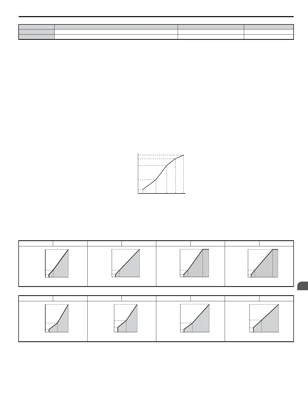
The user can select one of 15 preset V/f patterns (setting = 0 through E) or decide to set a customized V/f pattern (setting = F). By selecting one of the 15
presets (settings 0 through E), the drive will automatically set the parameters listed in the table below.
E1-09 less than or equal to E1-07 less than or equal to E1-06 less than or equal to E1-11 less than or equal to E1-04
Output Voltage (V)
Frequency (Hz)
E1-05
E1-12
E1-13
E1-08
E1-10
E1-09 E1-07 E1-06 E1-11 E1-04
Figure 5.35 V/f Pattern
Note: When the drive is initialized using parameter A1-03, the setting of E1-03 is unaffected but the settings of E1-04 through E1-13 are returned to their default settings.
V/f Patterns for 0.1 to 3.7 kW Drives
The following graphs are for 200 V class drives. Double values when using a 400 V class unit.
Table 5.5 Constant Torque Characteristics, Settings 0 to 3
Setting = 0
50 Hz Setting = 1 60 Hz Setting = 2 60 Hz Setting = 3 72 Hz
Voltage (V)
Frequency (Hz)
0
12
200
1.3 2.5 50
16
Voltage (V)
Frequency (Hz)
0
12
16
200
1.5 3 60
Voltage (V)
Frequency (Hz)
0
12
16
200
1.5 3 6050
Voltage (V)
Frequency (Hz)
0
12
16
200
1.5 3 7260
Table 5.6 Derated Torque Characteristics, Settings 4 to 7
Setting = 4
50 Hz Setting = 5 50 Hz Setting = 6 60 Hz Setting = 7 60 Hz
Voltage (V)
Frequency (Hz)
0
8
200
1.3 25 50
35
Voltage (V)
Frequency (Hz)
0
9
200
1.3 25 50
50
Voltage (V)
Frequency (Hz)
0
8
200
1.5 30 60
35
Voltage (V)
Frequency (Hz)
0
9
200
1.5 30 60
50
5.5 E: Motor Parameters
YASKAWA ELECTRIC SIEP C710606 18A YASKAWA AC Drive – V1000 Technical Manual (Preliminary)
147
5
Parameter Details

 Loading...


