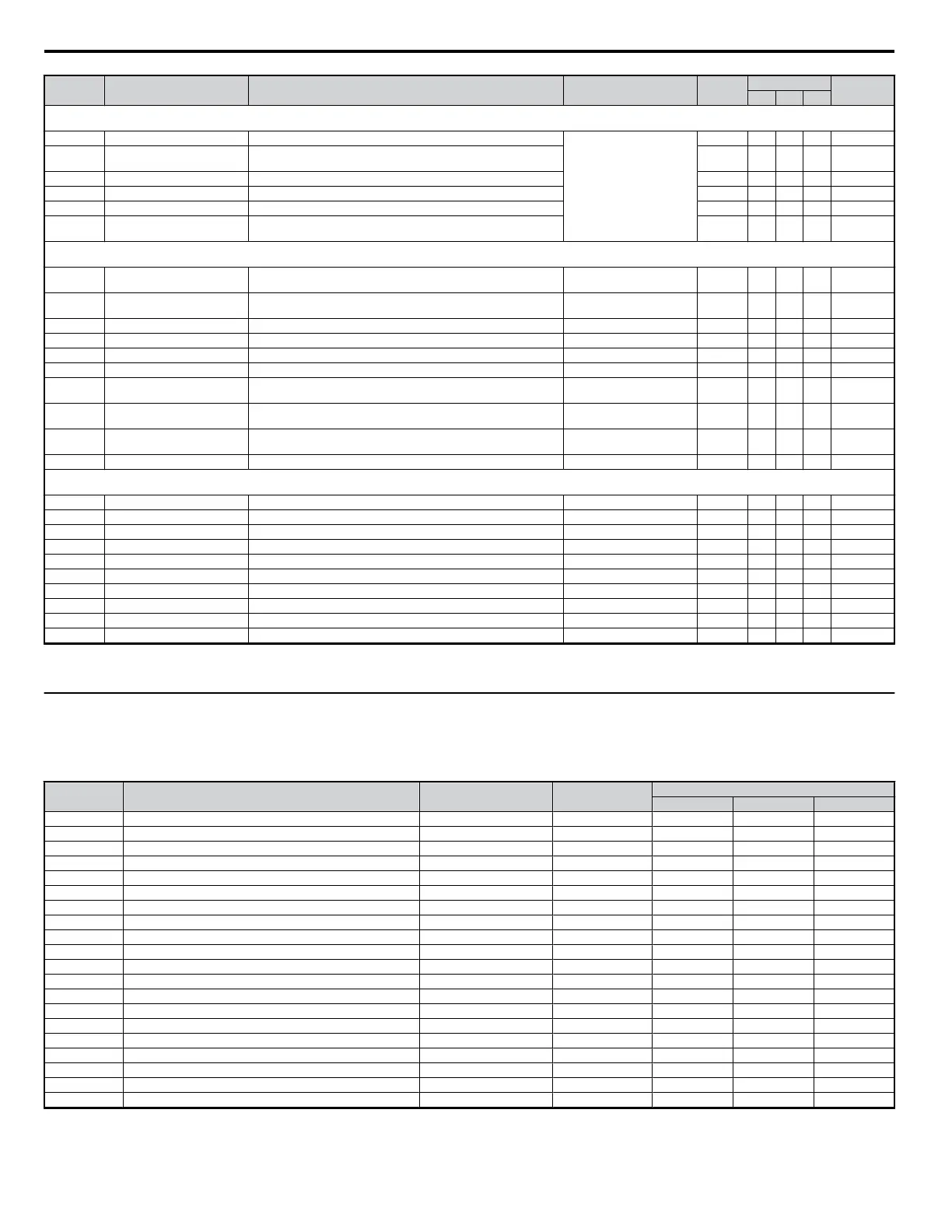
No. Name Description Analog Output Level Unit
Control Mode
Addr. Hex
V/f OLV PM
U5: Application Monitor
Use U5 parameters to view application-specific settings.
U5-01 PID Feedback Displays the PID feedback value in.
10V: 100% (max. freq.)
0.01% A A A 57
U5-02 PID Input
Displays the amount of PID input (deviation between PID target and
feedback).
0.01% A A A 63
U5-03 PID Output Displays PID control output. 0.01% A A A 64
U5-04 PID Setpoint Displays the PID setpoint. 0.01% A A A 65
U5-05 PID differential feedback Displays the 2nd PID feedback value if differential feedback is used. 0.01% A A A
U5-06 PID Adjusted Feedback
Displays the subtraction value of both feedback values if differential
feedback is used.
0.01% A A A
U6: Application Monitor
Use U6 parameters to display drive control information.
U6-01 Motor Secondary Current (Iq) Displays the value of the motor secondary current (Iq).
10 V: Motor rated secondary
current
0.1% A A A 51
U6-02 Motor Excitation Current (ld)
Displays the value calculated for the motor excitation current (Id) as a
percentage of the motor rated secondary current (Iq).
10 V: Motor rated secondary
current
0.1% − A A 52
U6-03 ASR Input Displays the ASR input value if Simple PG is used in V/f control. 10V: 100% (max. freq.) 0.1% A − −
U6-04 ASR Output Displays the ASR output value if Simple PG is used in V/f control. 10V: 100% (max. freq.) 0.1% A − − 55
U6-05 Output voltage reference (Vq) Output voltage reference (Vq). (q-axis) 10 V: 200 V (400 V) 0.1 Vac − A A 59
U6-06 Output Voltage Reference (Vd) Output voltage reference (Vd). (d-axis) 10 V: 200 V (400 V) 0.1 Vac − A A 5A
U6-07 q-axis ACR Output
Displays the current control (ACR) output of for the motor secondary
current (Iq).
10 V: 100% 0.1% − A − 5F
U6-08 d-Axis ACR Output
Displays the current control (ACR) output of for the motor excitation
current (Id).
10 V: 100% 0.1% − A − 60
U6-20
Frequency Reference Bias (Up/
Down 2)
Displays the bias value used to adjust the frequency reference. 10 V: max. frequency 0.1% A A A 7D4
U6-21 Offset Frequency Displays the frequency added to the main frequency reference. 10 V: max. frequency 0.1% A A A 7D5
U8: Custom Monitors for DriveWorksEZ
U8 parameters are reserved for DriveWorksEZ
U8-01 – Reserved for DriveWorksEZ, Monitor 1. – 0.01% Α A Α 1950
U8-02 – Reserved for DriveWorksEZ, Monitor 2. – 0.01% A A A 1951
U8-03 – Reserved for DriveWorksEZ, Monitor 3. – 0.01% A A A 1952
U8-04 – Reserved for DriveWorksEZ, Monitor 4. – 0.01% A A A 1953
U8-05 – Reserved for DriveWorksEZ, Monitor 5. – 0.01% A A A 1954
U8-06 – Reserved for DriveWorksEZ, Monitor 6. – 0.01% A A A 1955
U8-07 – Reserved for DriveWorksEZ, Monitor 7. – 0.01% A A A 1956
U8-08 – Reserved for DriveWorksEZ, Monitor 8. – 0.01% A A A 1957
U8-09 – Reserved for DriveWorksEZ, Monitor 9. – 0.01% A A A 1958
U8-10 – Reserved for DriveWorksEZ, Monitor 10. – 0.01% A A A 1959
<27> Setting units for this parameter are determined by o2-04, Drive/kVA Selection. Less than 11 kW: 2 decimal points, 11 kW and above: 1 decimal point.
<60> Available for the drive software version 1011 or later.
u
Control Mode Dependent Parameter Default Values
The tables below list parameters that depend on the control mode selection (A1-02 for motor 1, E3-01 for motor 2). These parameters are initialized to
the shown values if the control mode is changed.
Table B.1 A1-02 (Motor 1 Control Mode) Dependent Parameters and Default Values
No. Description Setting Range Resolution
Control Modes (A1-02)
V/f (0) OLV (2) PM (5)
b3-02 Speed Search deactivation current 0 to 200 1% 120 100 –
b8-02 Energy Saving gain 0.0 to 10.0 0.1 – 0.7 –
C2-01 S-curve time at acceleration start 0.00 to 10.00 0.01 s 0.20 0.20 1.00
C3-01 Slip compensation gain 0.0 to 2.5 0.1 0.0 1.0 –
C3-02 Slip compensation time constant 0 to 10000 1 msec 2000 200 –
C4-01 Torque comp. gain 0.00 to 2.50 0.01 1.00 1.00 0.00
C4-02 Torque comp. primary delay time 0 to 10000 1 msec 200 20 100
C6-02 Carrier frequency 1 to F 1 7 <12> 7 <12> 2
E1-04 Maximum output frequency 40.0 to 400.0 0.1 Hz 60.0 60.0 <10>
E1-05 Maximum output voltage <24> 0.0 to 255.0 0.1 V 230.0 230.0 <10>
E1-06 Base Frequency 0.0 to 400.0 0.1 Hz 60.0 60.0 <10>
E1-07 Middle output frequency 0.0 to 400.0 0.1 Hz 3.0 3.0 –
E1-08 Middle output freq. voltage <24> 0.0 to 255.0 0.1 V 18.4 13.8 –
E1-09 Minimum output frequency 0.0 to 400.0 0.1 Hz 1.5 0.5 <10>
E1-10 Minimum output voltage <24> 0.0 to 255.0 0.1 V 13.8 2.9 –
E1-11 Middle output frequency 2 0.0 to 400.0 0.1 Hz 0.0 0.0 –
E1-12 Middle output freq. voltage 2 <24> 0.0 to 255.0 0.1 V 0.0 0.0 –
E1-13 Base voltage <24> 0.0 to 255.0 0.1 V 0.0 0.0 –
L1-01 Motor protection selection 0 to 4 - 1 1 4
L3-20 Accel/Decel rate calculation rate 0.00 to 5.00 0.01 1.00 0.30 0.65
B.2 Parameter Table
322
YASKAWA ELECTRIC SIEP C710606 18A YASKAWA AC Drive – V1000 Technical Manual (Preliminary)

 Loading...


