C.1 MEMOBUS/Modbus Hardware
Yaskawa drives can be controlled with a PLC using the MEMOBUS/Modbus protocol to conduct serial communications.
MEMOBUS/Modbus communication can be configured using one master (PLC) and a maximum of 31 slaves. Serial communication between master and
slave are normally started by the master and the slaves respond.
The master performs serial communications with only one slave at a time. The address or node for each slave must be set beforehand so that the master
can perform serial communications using that address. A slave that receives a command from the master performs the specified function and sends a
response back to the master.
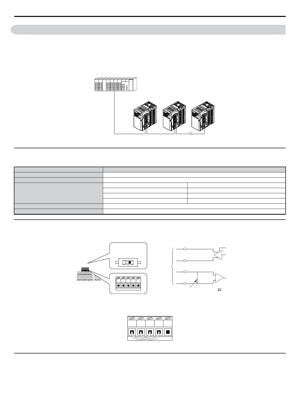
PLC (MEMOCON SERIES OR OTHER)
DRIVE DRIVE DRIVE
Figure C.1 Connecting Multiple Drives to a PLC
u
Communication Specifications
MEMOBUS/Modbus specifications appear in the following table:
Item Specifications
Interface RS-422, RS-485
Communications Cycle Asynchronous (Start-stop synchronization)
Communication Parameters
Communication Speeds Available 12, 24, 48, 96, 192, 384, 576, 768, 1152 kbps
Data length 8 bits (fixed)
Parity Select even, odd, or none.
Stop bit 1 bit (fixed)
Protocol MEMOBUS/Modbus (using RTU mode only)
Max Number of Connections 31 drives (using RS-485)
u
Communication Terminal Resistance
The MEMOBUS/Modbus communication uses the following terminals: S+, S-, R+, and R-. Enable the terminating resistance by setting pin 1 of DIP
switch S2 to the ON position.
S1 S2 S3 S4 S5 S6 S7 HC SC H1 RP
R+
P1 P2 PC A1 A2 +V AC AM AC MP
MCMBMA
R-
S+ S- IG
+
-
R+ R- S+ S- IG
R+
R
-
S+
S
-
RS-422A
or
RS-485
DIP
switch
S2
DIP switch S2
(in the ON position)
OFF ON
terminal resistance (1/2 W, 110 )
Figure C.2 Serial Communications Terminal and DIP Switch S2
Note: Separate the communications cables from the main circuit cables and other wiring and power cables. Use shielded cables for the communications cables, and properly shielded
clamps to prevent problems with noise. When using RS-485 communications, connect S+ to R+, and S- to R- as shown in the diagram below.
R+
S+ IG
R-
S-
Figure C.3 RS-485 Terminal Wiring
u
Connecting a PLC
Follow the instructions below to connect the drive to a PLC.
C.1 MEMOBUS/Modbus Hardware
330
YASKAWA ELECTRIC SIEP C710606 18A YASKAWA AC Drive – V1000 Technical Manual (Preliminary)

 Loading...


