n
Jog Operation Procedures
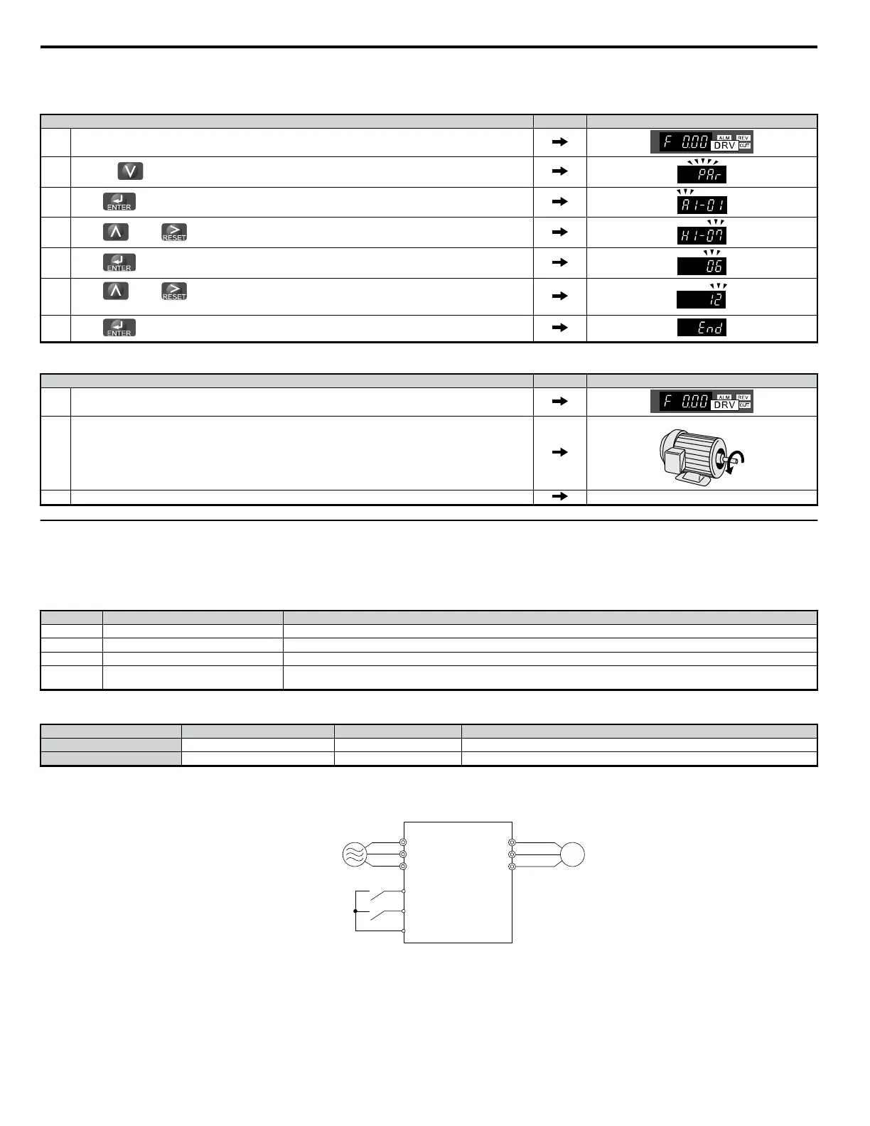
Set H1-07 (Multi-Function Contact Input Terminal S7 Function Selection) to “12” (FJOG command).
Step Display/Result
1. Turn the power on to the drive. The initial display appears.
2.
Press the key until the Parameter Setting menu appears.
3.
Press to enter the Parameter Setting menu.
4.
Press and until H1-07 appears. Note: Select a parameter between H1-01 and H1-07.
5.
Press and set the value for H1-07.
6.
Press and until “12” appears on the screen.
Note: At jog operation in reverse run, set multi-function contact input to 13.
7.
Press to save the setting.
To begin rotating the motor:
Step Display/Result
1.
Turn the power on to the drive. The initial display appears.
Note: Set the drive to REMOTE.
2.
With multi-function contact input terminal S7 closed, the motor rotates forwards at 6 Hz.
Note: No run command is necessary when using the Jog frequency.
Motor
3. The drive will stop with terminal S7 open.
u
Multi-Step Speed Operation (4-Step Speed)
Select up to 17 preset references (including Jog reference) using five multi-function inputs S3 through S7. Four multi-step references can be selected using
two multi-function inputs as illustrated in Figure 4.32 .
n
Multi-Step Speed Operation Parameters
No. Name Description
d1-01 Frequency Reference 1 Frequency reference. o1-03 determines the units, with Hz as the default.
d1-02 Frequency Reference 2
Frequency reference when multi-function input “Multi-Step Speed Reference 1" (H1-oo = 3) is on. Setting unit: set by o1-03.
d1-03 Frequency Reference 3
Frequency reference when multi-function input “Multi-Step Speed Reference 2” (H1-oo = 4) is on. Setting unit: set by o1-03.
d1-04 Frequency Reference 4
Frequency reference when multi-function input “Multi-Step Speed Reference 1, 2" (H1-oo = 3 and 4) are both on. Setting unit: set
by o1-03.
n
Digital Input
Terminal Parameter Setting Contents
S5 H1-05 3 Multi-Step Speed Reference 1
S6 H1-06 4 Multi-Step Speed Reference 2
n
Wiring Example
Set up external switches SW1 and SW2.
R/L1
S/L2
T/L3
U/T1
V/T2
W/T3
M
Three-Phase, 200 Vac
(AC400 V)
S5
S6
SW1
SW2
SC
Drive
Figure 4.32 Control Terminals for 4 Multi-Step Speeds
4.7 Test Run
98
YASKAWA ELECTRIC SIEP C710606 18A YASKAWA AC Drive – V1000 Technical Manual (Preliminary)

 Loading...


