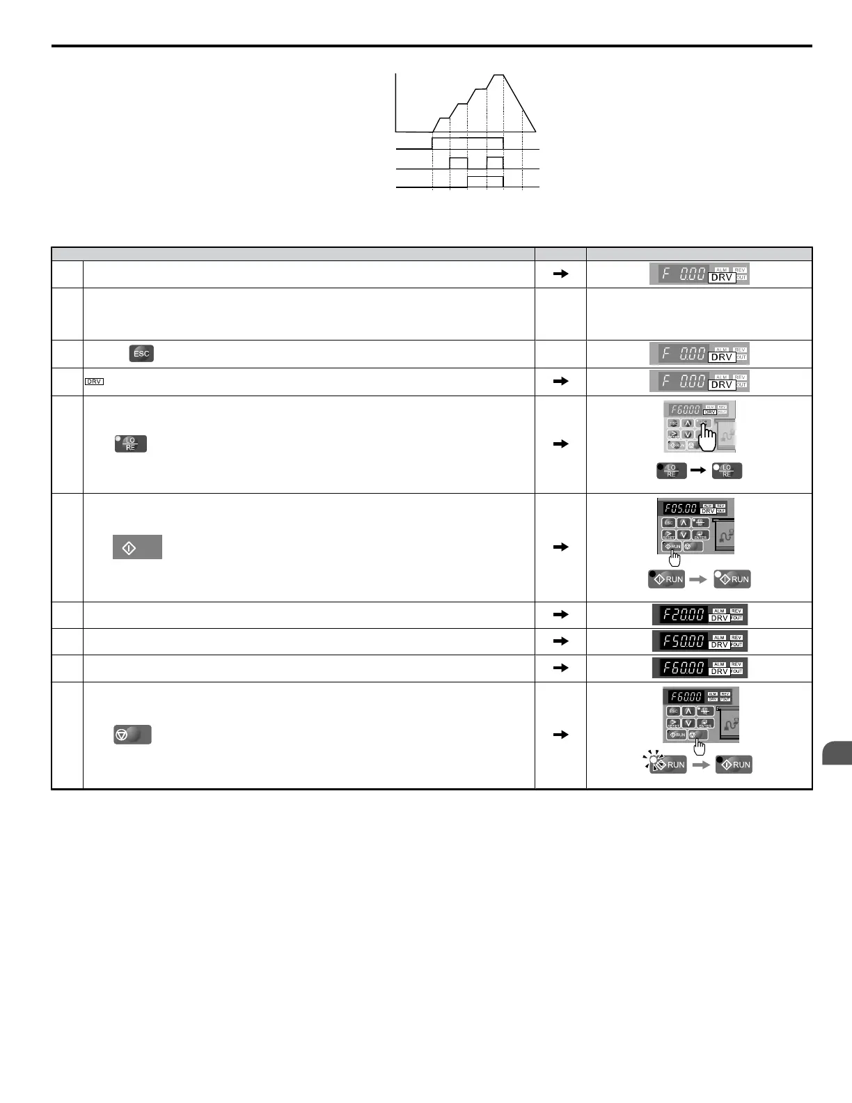
Freq Ref 3
Freq Ref 2
Freq Ref 1
Forward/Reverse Run/Stop
Multi-Step Speed 1
Multi-Step Speed 2
Frequency
Reference
ON
ON
ON
OFF
OFF
Freq Ref 4
ON
Figure 4.33 4-Step Speed Time Chart
n
Setting Procedure
Step Display/Result
1. Turn on the power to the drive. The initial display appears.
2.
Set the frequencies listed below to the specified parameters:
1. d1-01 = 5 Hz: Step 1 <1>
2. d1-02 = 20 Hz: Step 2 <2>
3. d1-03 = 50 Hz: Step 3
4. d1-04 = 60 Hz: Step 4
3.
Press the key until the initial display appears.
4. turns on.
5.
Press to select LOCAL. The LO/RE light will turn on.
Off On
6.
Press
RUN
to run the motor at 5 Hz. The RUN light will turn on.
Off On
7. With SW1 closed, the drive runs the motor at Multi-Step Speed 2 (20 Hz).
8. With SW1 open and SW2 closed, the drive runs the motor at Multi-Step 3 (50 Hz).
9. With both SW1 and SW2 closed, the drive runs the motor at Multi-Step 4 (60 Hz).
10.
Press
STOP
to stop the drive. The RUN light will flash until the motor comes to a complete stop.
Flashing Off
<1> When the frequency reference is assigned to the LED operator (b1-01=0), the first step in a multi-step speed sequence comes from d1-01.
<2> Set H3-10 (Multi-function Analog Input (current) Terminal A2 Function Selection) to “F” (not used).
Note: When a run command is input from the control circuit terminal, the frequency reference value is selected as follows: When b1-01 = 0 and the run command is given, the drive
uses the frequency set to d1-01. When b1-01 = 1 and the run command is given, the drive uses the frequency reference value input to analog control terminal A1.
4.7 Test Run
YASKAWA ELECTRIC SIEP C710606 18A YASKAWA AC Drive – V1000 Technical Manual (Preliminary)
99
4
Start-Up Programming
& Operation

 Loading...


