WARNING! Fire Hazard. When using a braking unit, use a thermal relay on the braking resistors and configure a fault contact output for the braking resistor unit to disconnect drive
main power via an input contactor. Inadequate braking circuit protection could result in death or serious injury by fire from overheating resistors.
u
Connecting an AC or DC Reactor
AC and DC reactors suppress surges in current and improve the power factor on the input side of the drive.
To better suppress harmonic current, use an AC reactor and DC reactor together.
Use a DC reactor or AC reactor or both:
• To suppress harmonic current or improve the power factor of the power supply.
• When using an advancing capacitor switch.
• With a large capacity power supply transformer (over 600 kVA).
Note: Use an AC or DC reactor when also connecting a thyristor converter (such as a DC drive) to the same power supply system, regardless of the conditions of the power supply.
n
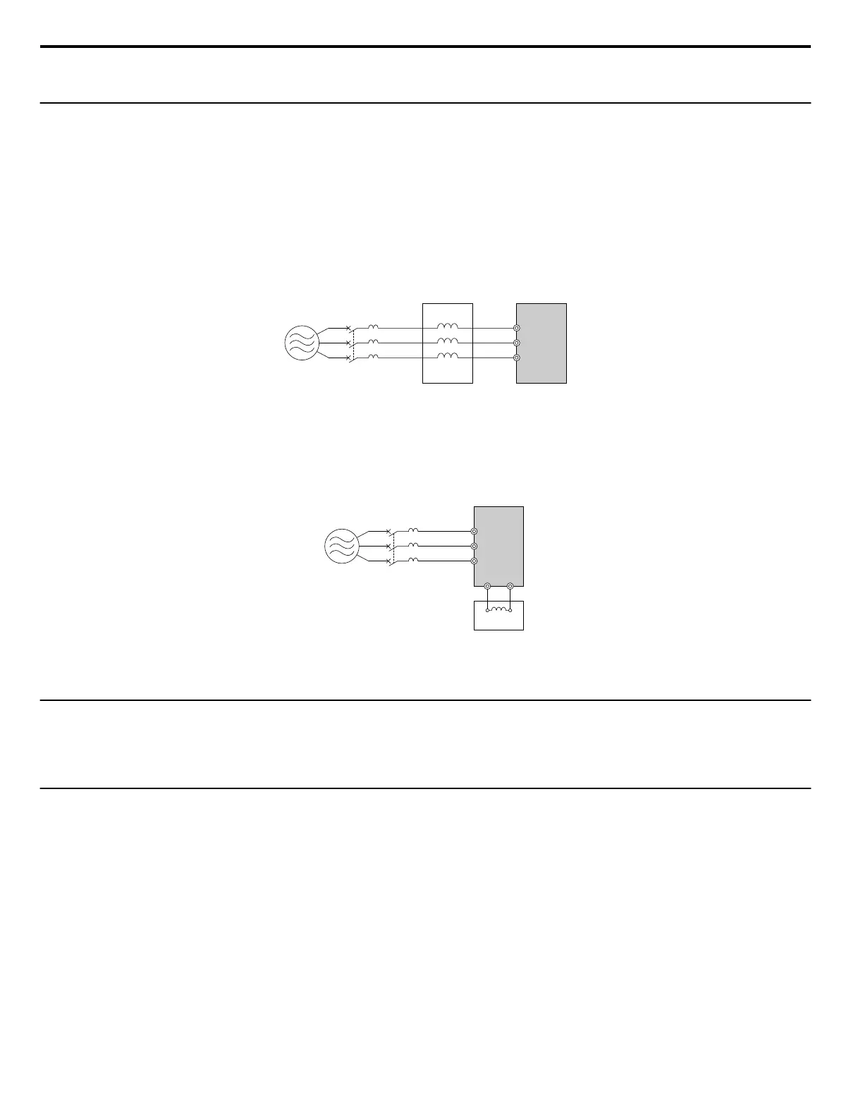
Connecting an AC Reactor
BA
C D
R/L1U
V
W
X
Y
Z
S/L2
T/L3
A – Power supply
B – MCCB
C – AC reactor
D – Drive
Figure 8.4 Connecting an AC Reactor
n
Connecting a DC Reactor
Ensure the jumper between terminals +1 and +2 (terminals are jumpered for shipment) is removed when connecting a DC reactor. The jumper must be
installed if no DC reactor is used. Refer to
Figure 8.5 for an example of DC reactor wiring.
A
C
D
R/L1
+1 +2
B
S/L2
T/L3
A – Power supply
B – MCCB
C – Drive
D – DC reactor
Figure 8.5 Connecting a DC Reactor
u
Connecting a Surge Protector
A surge protector suppresses surge voltage generated from switching an inductive load near the drive. Inductive loads include magnetic contactors, relays,
valves, solenoids and brakes. Always use a surge protector or diode when operating with an inductive load.
Note: Never connect a surge protector to the drive output.
u
Connecting a Noise Filter
n
Input-Side Noise Filter
Drive outputs generate noise as a result of high-speed switching. This noise flows from inside the drive back toward the power supply, possible affecting
other equipment. Installing a noise filter to the input side of the drive can reduce the amount of noise flowing back into the power supply. This also prevents
noise from entering the drive from the power supply.
• Use a noise filter specifically designed for AC drives.
• Install the noise filter as close as possible to the drive.
8.4 Installing Peripheral Devices
272
YASKAWA ELECTRIC SIEP C710606 18A YASKAWA AC Drive – V1000 Technical Manual (Preliminary)

 Loading...


