B C
D
A
R/L1
1
2
3
4
E
MCCB
MCCB
S/L2
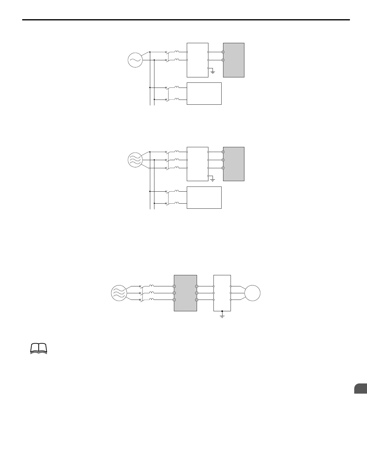
A – Power supply
B – Input-side noise filter Model: LNFD-
oo
C – Drive
D – Other control device
Figure 8.6 Input-Side Noise Filter (Single-Phase 200 V)
C
D
A
B
R/L1
U
V
W
R
S
T
E
MCCB
MCCB
S/L2
T/L3
A – Power supply
B – Input-side noise filter Model: LNFD-
oo
C – Drive
D – Other control device
Figure 8.7 Input-Side Noise Filter (Three-Phase 200/400 V)
n
Output-Side Noise Filter
A noise filter on the output side of the drive reduces inductive noise and radiated noise.
Figure 8.8 illustrates an example of output-side noise filter
wiring.
NOTICE: Do not connect phase-advancing capacitors or LC/RC noise filters to the output circuits. Improper application of noise filters could result in damage to the drive.
C
B
A
D
R/L1
MCCB
S/L2
T/L3
U/T1
V/T2
W/T3
1
2
3
4
5
6
A – Power supply
B – Drive
C – Output-side noise filter
D – Motor
Figure 8.8 Output-Side Noise Filter
TERMSTERMS
Radiated noise:
• Electromagnetic waves radiated from the drive and cables create noise throughout the radio bandwidth that can affect devices.
Induced noise:
• Noise generated by electromagnetic induction can affect the signal line and may cause the controller to malfunction.
Preventing Induced Noise
Use a noise filter on the output side or use shielded cables. Lay the cables at least 30 cm away from the signal line to prevent induced noise.
8.4 Installing Peripheral Devices
YASKAWA ELECTRIC SIEP C710606 18A YASKAWA AC Drive – V1000 Technical Manual (Preliminary)
273
8
Peripheral Devices &
Options

 Loading...


