5.12 U: Monitor Parameters
Monitor parameters let the user view various aspects of drive performance as it is displayed on the operator screen.
u
U1: Status Monitors
The following monitors display drive status. The data displayed when viewing the parameters below can also be output from terminal AM by assigning
the specific monitor parameter number to H4-01. This is done by setting the numeric parts of Uo-oo to H4-01. For more information,
Refer to H4:
Multi-Function Analog Output Terminals on page 182.
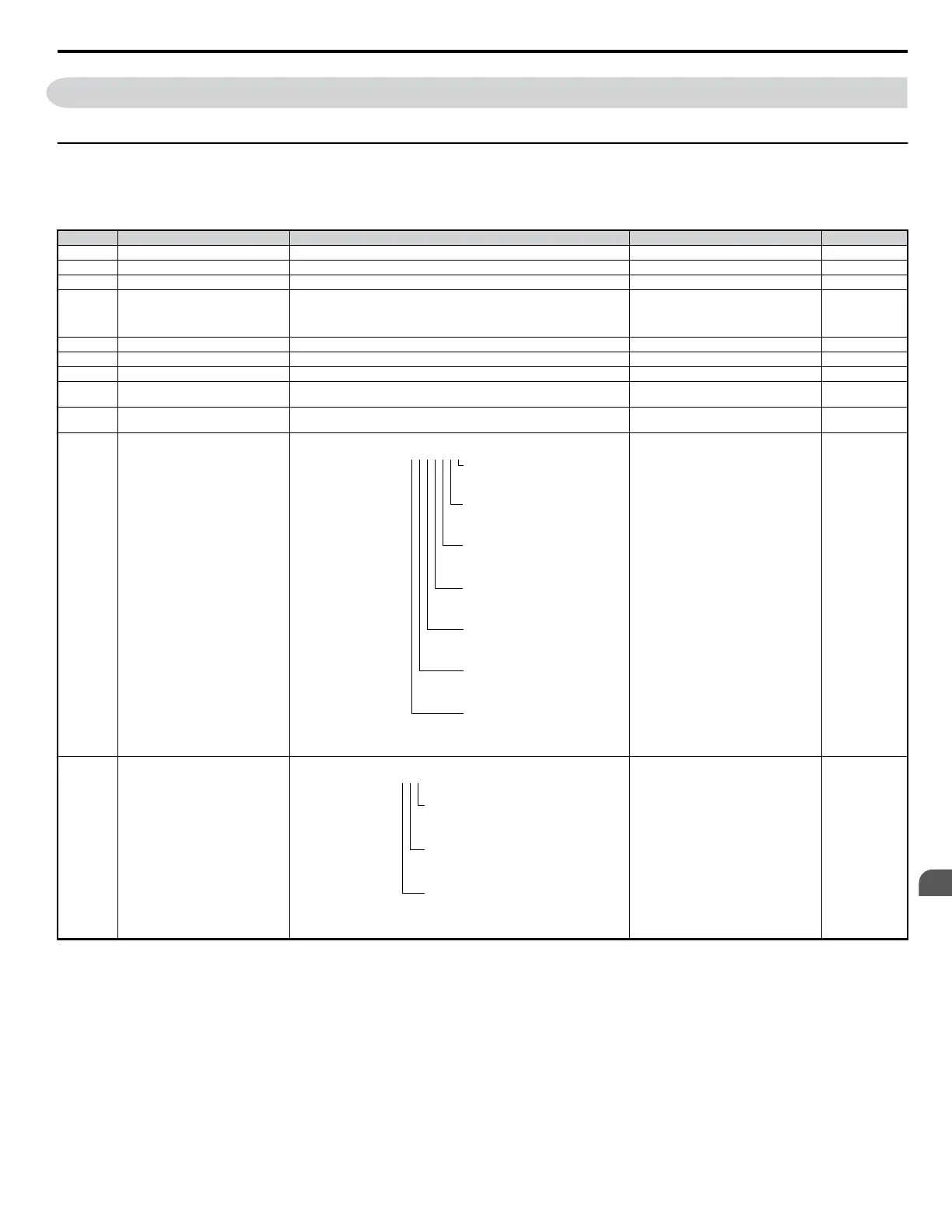
No. Name Description Analog Output Level Unit
U1-01 Frequency Reference Monitors the frequency 10 V: Max frequency 0.01Hz
U1-02 Output Frequency Displays the output voltage. Display units are determined by o1-03. 10 V: Max frequency 0.01Hz
U1-03 Output Current Displays the output current. 10 V: Drive rated current 0.01A
U1-04 Control Mode
Control method set in A1-02.
0: V/f without PG
2: Open Loop Vector (OLV)
5: PM Open Loop Vector (PM)
No output signal available –
U1-05 Motor Speed Displays the motor speed feedback. Display units are determined by o1-03. 10 V: Maximum speed 0.01Hz
U1-06 Output Voltage Reference Displays the output voltage. 10 V: 200 Vrms (400 Vrms) 0.1 V
U1-07 DC Bus Voltage Displays the DC bus voltage. 10 V: 400 V (800 V) 1 V
U1-08 Output Power Displays the output voltage (this value is determined internally).
10 V: Drive capacity (kW) (max. motor
capacity allowed)
–
U1-09 Torque Reference
Monitor of internal torque reference value for Open Loop Vector (OLV)
control
10 V: Motor rated torque –
U1-10 Input Terminal Status
Displays the input terminal status.
U1-09
=
0 0 0 0 0 0 0
1: FWD run
command
(terminal S1
enabled)
1: REV run
command
(terminal S2
enabled)
1: Multi-Function
Digital
Input 1 (terminal
S3 enabled)
1: Multi-Function
Digital
Input 2 (terminal
S4 enabled)
1: Multi-Function
Digital
Input 3 (terminal
S5 enabled)
1: Multi-Function
Digital
Input 4 (terminal
S6 enabled)
1: Multi-Function
Digital
Input 5 (terminal
S7 enabled)
No output signal available –
U1-11 Output Terminal Status
Displays the output terminal status.
U1-11
=
0 0 0
1: Multi-Function
Digital Output (fault)
(terminal MA/MB-MC)
1: Multi-Function
Digital Output 1
(terminal P1) enabled
1: Multi-Function
Digital Output 2
(terminal P2) enabled
No output signal available –
5.12 U: Monitor Parameters
YASKAWA ELECTRIC SIEP C710606 18A YASKAWA AC Drive – V1000 Technical Manual (Preliminary)
215
5
Parameter Details

 Loading...


