D.4 Safe Disable Input Precautions
u
Safe Disable Function Description
The Safe Disable function can be utilized to perform a safe stop following the EN60204-1, stop category 0 (Uncontrolled stop by power removal). It is
designed to meet the requirements of the EN954-1, Safety Category 3 and EN61508, SIL2.
Removing the voltage from the terminal H1 activates the disables the drive output, i.e. the power supply to the motor is cut by stopping the switching of
the output transistors in a safe way and “Hbb” is shown in the display. Safe Disable is applicable for induction and permanent magnet motors.
u
Installation
• If the Safe Disable function is utilized, the wire link between the terminals HC and H1, which is preinstalled at the shipment, has to be removed entirely.
• Connect the drive to an EN954-1, Safety Category 3 interrupting device so that in case of a safe stop request the connection between the terminals HC
and H1 is opened.
• Wiring for the safety input should be kept under 30 meters.
Note: Drive output is interrupted in less than 1 ms after the safety input is activated.
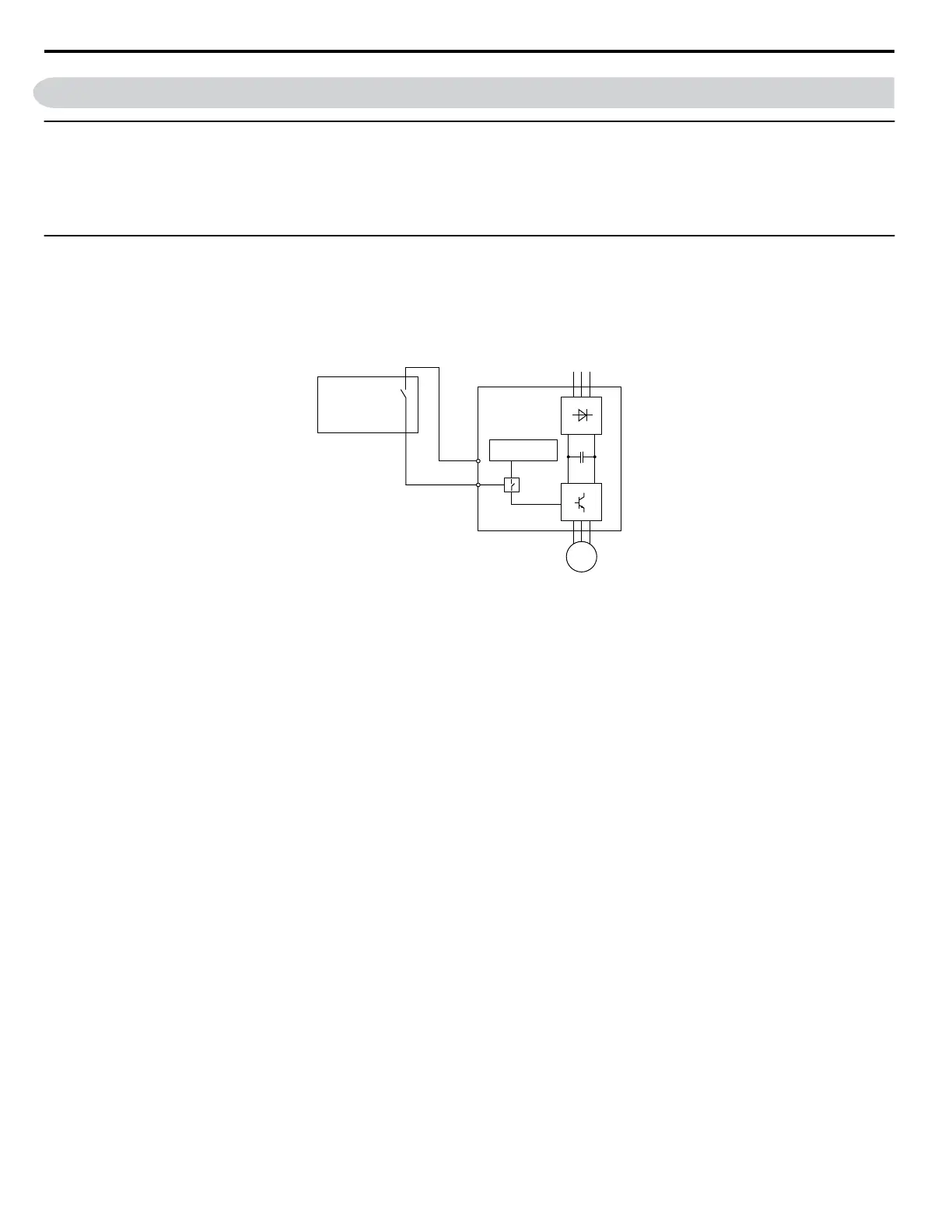
Power Supply
Controller
HC
H1
EN954-1 Safety
Cat, 3 Device
M
Drive
Figure D.9 Safe Disable Wiring Example
Note: 1. To assure that the Safe Disable function appropriately fulfills the safety requirements of the application, a throughout risk assessment for the whole safety system has to be
carried out.
2. The drive must be installed in a cabinet with a protection degree of at least IP54 in order to maintain EN954-1, safety category 3 compliance.
3. If the safety device and the drive are installed in separate cabinets, the Safe Disable wires must be installed in a short circuit proof way.
4. The Safe Disable function does not cut the power supply to the drive and does not provide electrical isolation. Before any installation or maintenance work is done, the
drives power supply must be switched off.
5. When PM motors are used, the following must be considered:
Even if the HWBB function is active, although unlikely a failure in two of the drives power devices can occur which means that current flows through the motor winding.
In an induction motor no torque can be produced by that. However, if this happens and a PM motor is connected a torque is produced causing an alignment of the rotor
magnets. The rotor may turn up to 180 degrees electrically. It must be ensured, that this possible failure mode is not safety critical for the application.
6. The time from opening the Safe Disable input until the drive output is switched off is less than 1 ms.
D.4 Safe Disable Input Precautions
356
YASKAWA ELECTRIC SIEP C710606 18A YASKAWA AC Drive – V1000 Technical Manual (Preliminary)

 Loading...


