No. Parameter Name Description Setting Range Default
A2-01
to
A2-32
Preferred
Parameters1 to 32
Parameters selected by the user are stored to the User Parameter menu. This includes recently viewed parameters or
parameters specifically selected for quick access.
If parameter A2-33 is set to 1, recently viewed parameters will be listed between A2-17 and A2-32. Parameters A2-01
through A2-16 must be manually selected by the user.
If A2-33 is set to 0, then recently viewed parameters will not be saved to the User Parameter group. The entire A2
parameter group is now available for manual programming.
b1-01 to o2-08 –
A2-33
Preferred Parameter
Automatic Selection
0: Parameters A2-01 through A2-32 are reserved for the user to create a list of User Parameters.
1: Save history of recently viewed parameters. Recently edited parameters will be saved to A2-17 through A2-32 for
quick access. The most recently changed parameter is registered in A2-17. The second most recently changed parameter
is registered in A2-18.
0, 1 1
n
Password Settings: A1-04, A1-05
The user can set a password to the drive to restrict access. The password is selected via parameter A1-05. The selected password must be entered in
parameter A1-04 to unlock parameter access (i.e., parameter setting A1-04 must match the value programmed into A1-05). The following parameters
cannot be viewed or edited until the value programmed into A1-04 correctly matches the value as programmed in parameter A1-05: A1-01, A1-02, A1-03,
A1-06 and A2-01 through A2-33.
Note:
Parameter A1-05 is hidden from view. To display A1-05, access parameter A1-04 and simultaneously depress the
key and the key.
n
Copy Function (Optional)
Using an option, the parameter setting can be copied to another drive. Storing the modified contents can make restoration easy since the parameters do
not have to be set from the beginning if the drive breaks down and must be replaced. For this drive, the following two options can be used:
• Copy unit with USB (USB converter with copy function)
• Drive Wizard (Parameter management tool of PC application software)
Copy Unit with USB
Connect and exclusive-use cable to the communication connector on the drive and use the ON/OFF switch on the copy unit with USB to copy the data
Drive Wizard
Use Drive Wizard to copy the parameter setting to another drive. For details, refer to Help in the Drive Wizard software.
u
Jog Operation: FJOG/RJOG
Digital inputs programmed as Forward Jog (H1-oo = 12) and Reverse Jog (H1-oo = 13) will be Jog inputs that do not require a run command. Closing
the terminal set for Forward Jog input will cause the drive to ramp to the Jog Frequency Reference (d1-17) in the forward direction. The Reverse Jog will
cause the same action in the reverse direction. The Forward Jog and Reverse Jog can be set independently.
n
Jog Operation Parameters
No. Name Description Setting Range Default Setting
d1-17 Jog Frequency Reference
Frequency reference when: “Jog Frequency Reference” is selected via multi-function input terminals. “Jog
Frequency Reference” has priority over “Multi-Step Speed Reference 1 to 16." Parameter d1-17 is also the
reference for the JOG key on the digital operator, and the multi-function inputs “Forward Jog” and “Reverse
Jog.”
0.00 to 400.00 6.00 Hz
n
Selections for Digital Input Terminals S1 to S7 (H1-01 to H1-07)
Setting Name
12 FJOG Command (ON: rotates forward at the Jog frequency set to d1-17)
13 RJOG Command (ON: rotates in reverse at the Jog frequency set to d1-17)
n
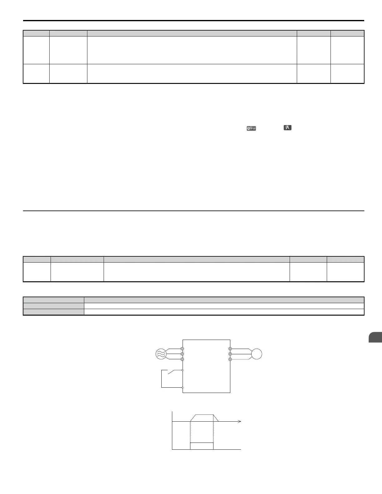
Connection Example for the Jog Function
In this example, H1-07 = 12 and d1-17 = 6.0 Hz.
R/L1
S/L2
T/L3
U/T1
V/T2
W/T3
M
Three-Phase 200 Vac
(400 Vac)
S7 (FJ0G)
SC
Drive
Figure 4.30 Jog Command from External Terminals
6.0 Hz
ON
Output
Frequency
Jog Reference
(FJ0G)
Figure 4.31 Jog Operation Pattern
4.7 Test Run
YASKAWA ELECTRIC SIEP C710606 18A YASKAWA AC Drive – V1000 Technical Manual (Preliminary)
97
4
Start-Up Programming
& Operation

 Loading...


