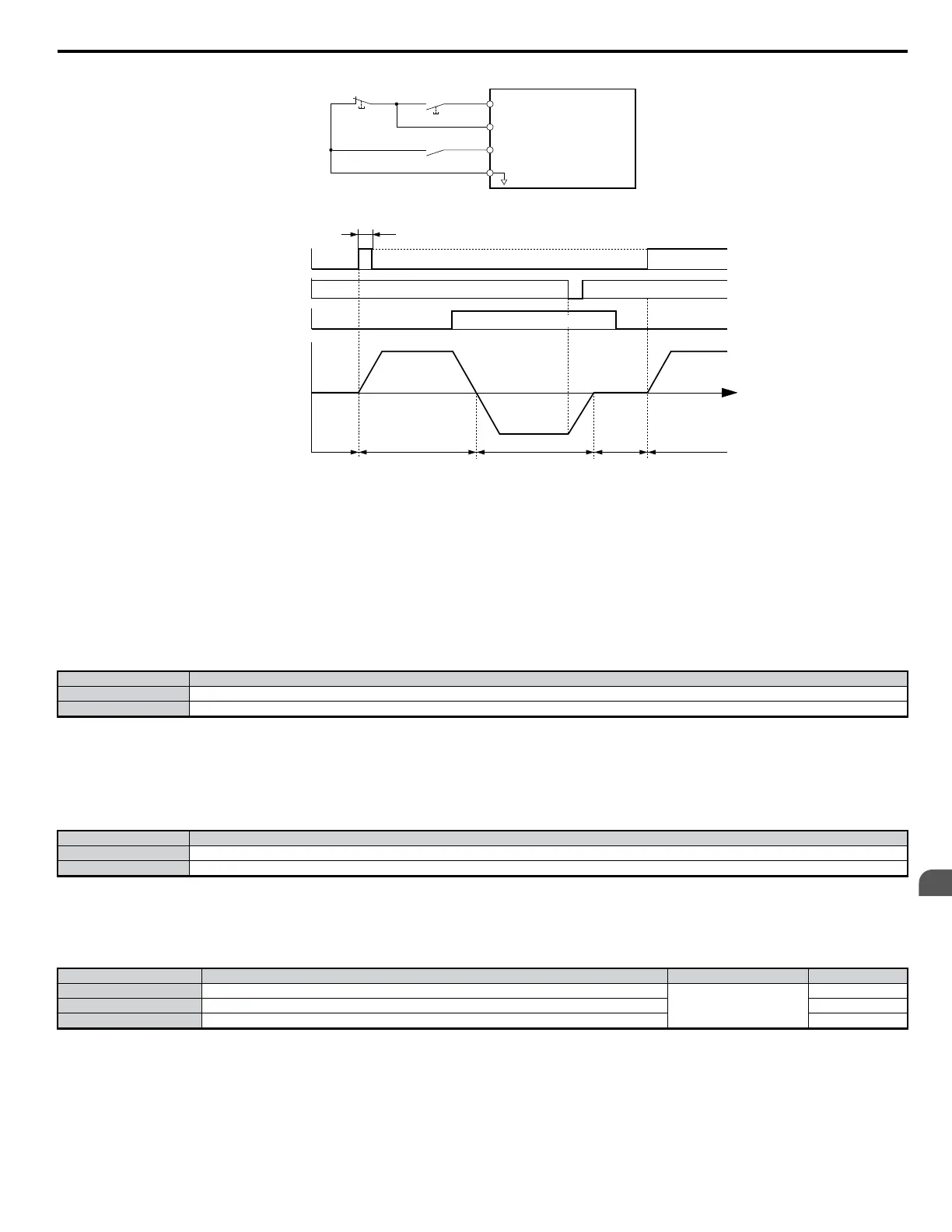
S1
S2
S5
SC
Run Command (Runs when Closed)
DRIVE
Stop Switch
(N.C.)
Run Switch
(N.O.)
Stop Command (Stops when Open)
FWD/REV (Multi-Function Input)
(H1-05 = 0)
Sequence Input Common
Figure 5.38 3-Wire Sequence Wiring Diagram
50 ms min.
Run command
OFF (stopped)
ON (reverse)
Stop Reverse Stop Foward
TIME
Can be either ON or OFF
OFF (forward)
Forward
Motor speed
Forward/reverse
command
Stop command
Figure 5.39 3-Wire Sequence
WARNING! Sudden Movement Hazard. The drive may start unexpectedly if the run command is already applied when programming 3-wire control. Set b1-17 to “0” and set terminal
S5 for a 3-wire sequence (H1-05 = 0). Failure to comply could result in death or serious injury from moving equipment.
WARNING! Sudden Movement Hazard. The motor will begin rotating when the power is turne on. may start unexpectedly if the run command is already applied when programming
3-wire control. Set b1-17 to “0” and set terminal S5 for a 3-wire sequence (H1-05 = 0). Failure to comply could result in death or serious injury from moving equipment.
Note: When terminal S1 set for the run command closes, the drive will start operating the motor after 50 ms. If the Run command is not given at power up (b1-17 = 0), the LED will
flash briefly when the power supply is cycled to indicate that protective functions are operating. Set b1-17to 1 to allow for the Run command to be given when the drive is
first powered on.
Setting 1: LOCAL/REMOTE Selection
When the Run command is assigned to the LED operator, this setting is called LOCAL. When the Run command is entered from one of the control circuit
terminals or from an upper controller sequence, this is referred to as REMOTE. This setting allows the input terminal to determine if the drive will run in
LOCAL mode or REMOTE mode.
Status Description
Open LOCAL: Operation according to frequency reference and Run command from digital operator.
Closed REMOTE: Operation according to frequency reference and Run command set by parameters b1-01 and b1-02, respectively.
Note: If one of the multi-function input terminals is set to for LOCAL/REMOTE, then the LO/RE key on the operator will be disabled. The drive cannot switch between LOCAL
and REMOTE during run. When the drive is set to LOCAL, the LO/RE LED will light.
Setting 2: Option/Drive Selection
The Option/Drive Selection function allows the user to select the source for the Run command and frequency references between either the drive’s terminals
or an optional communication board. When a digital input is programmed for the Option/Drive Selection function (H1-oo = 2), that input will function
as shown in the following table:.
Input Selection Status Source of Run Command and Frequency Reference
Open b1-01, b1-02
Closed b1-15, b1-16
Setting 3 to 5: Multi-Speed Reference 1 to 3
Setting 6: Jog Frequency Reference Selection
The drive can be programmed to utilize digital inputs to change between 16 presets speeds and a Jog speed. It is a two-step process to set the drive up for
preset speeds. Refer to d1-01 to d1-16: Frequency Reference 1 to 16 on page 139
No. Parameter Name Setting Range Default
d1-01 Frequency Reference 1 (when the source of the frequency reference is assigned to the operator)
0.00 to 400.00
0.00 Hz
d1-02 to d1-16 Frequency Reference 2 to 16 0.00 Hz
d1-17 Jog Frequency Reference 6.00 Hz
When a digital input configured as Jog Frequency Reference (H1-oo = 6) is closed, the active frequency reference will be the setting of parameter d1-17
(Jog Frequency Reference). Closure of this digital input alone will not initiate a Jog motion, it will only change the frequency reference. An active Run
command is necessary for the drive to operate at the Jog frequency reference. To change to the Jog frequency reference and provide a Run command with
a single input, refer to digital input settings 12 and 13.
Note: The Jog frequency reference overrides other frequency references.
Setting 7: Accel/Decel Time Selection 1
5.7 H: Terminal Functions
YASKAWA ELECTRIC SIEP C710606 18A YASKAWA AC Drive – V1000 Technical Manual (Preliminary)
161
5
Parameter Details

 Loading...


