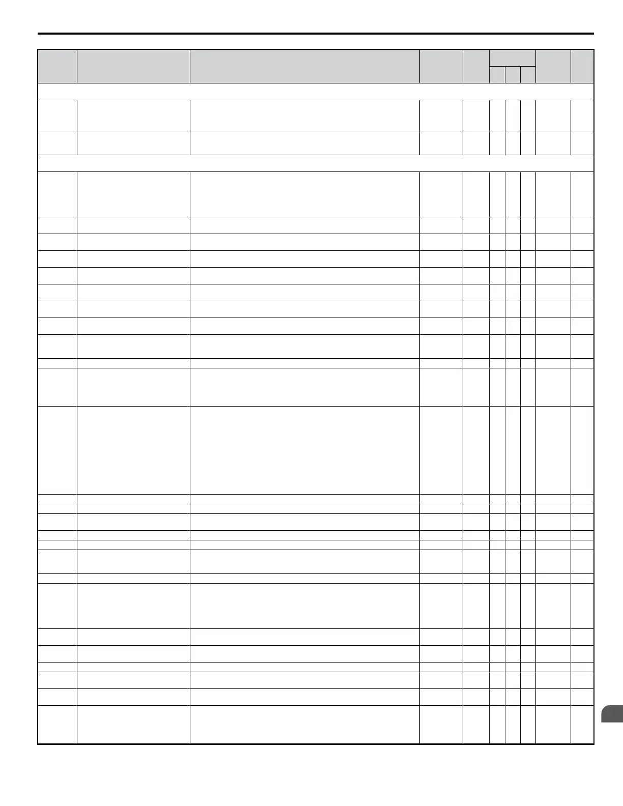
No. Name Description Range Def.
Control
Mode
Addr.
Hex
Pg.
V/f
OL
V
PM
b4: Timer Function
Use b4 parameters to configure timer function operation.
b4-01
Timer Function On-Delay Time
Used in conjunction with a multi-function digital input (H1-oo = 18) and a
multi-function digital output (H2-oo = 12) programmed for the timer function.
This sets the amount of time between digital input closure and digital output
activation.
0.0 to 300.0 0.0 s A A A 1A3 —
b4-02 Timer Function Off-Delay Time
Used in conjunction with a multi-function digital input (H1- = 18) and a multi-
function digital output programmed for the timer function. This sets the amount
of time the output remains activated after the digital input is opened.
0.0 to 300.0 0.0 s A A A 1A4 —
b5: PID Control
Use b5 parameters to configure the PID control drive function.
b5-01 PID Function Setting
Sets the PID control mode.
0: Disabled
1: Enable (Deviation is D-controlled)
2: Enable (Feedback is D-controlled)
3: Enable (Deviation is D-controlled, PID output added to Freq. Ref.)
4: Enable (Feedback is D-controlled, PID output added to Freq. Ref.)
0 to 4 0 A A A 1A5 —
b5-02 <22>
Proportional Gain Setting (P)
Sets the proportional gain of the PID controller. A setting of 0.00 disables P
control.
0.00 to 25.00 1.00 A A A 1A6 —
b5-03 <22>
Integral Time Setting (I)
Sets the integral time for the PID controller. A setting of 0.0 s disables integral
control.
0.0 to 360.0 1.0 s A A A 1A7 —
b5-04 <22>
Integral Limit Setting Sets the maximum output possible from the integrator. 0.0 to 100.0 100.0% A A A 1A8 —
b5-05 <22>
Derivative Time (D) Sets D control derivative time. A setting of 0.00 s disables derivative control. 0.00 to 10.00 0.00 s A A A 1A9 —
b5-06 <22>
PID Output Limit Sets the maximum output possible from the entire PID controller. 0.0 to 100.0 100.0% A A A 1AA —
b5-07 <22>
PID Offset Adjustment Applies an offset to the PID controller output.
-100.0 to
+100.0
0.0% A A A 1AB —
b5-08 <22>
PID Primary Delay Time Constant Sets the amount of time for the filter on the output of the PID controller. 0.00 to 10.00 0.00 s A A A 1AC —
b5-09 PID Output Level Selection
Sets the PID controller output direction.
0: Normal Output (direct acting)
1: Reverse Output (reverse acting)
0, 1 0 A A A 1AD —
b5-10 PID Output Gain Setting Sets the gain applied to the PID output. 0.00 to 25.00 1.00 A A A 1AE —
b5-11 PID Output Reverse Selection
Sets the drive operation with negative PID output.
0: Drive stops with negative PID output
1: Rotation direction reverses with negative PID output.
When using setting 1 make sure, reverse operation is permitted by parameter
b1-04.
0, 1 0 A A A 1AF —
b5-12
PID Feedback Reference Missing
Detection Selection
Configures the PID feedback loss detection.
0: Disabled.
1: Feedback loss detected when PID enabled. Alarm output, operation is
continued without triggering a fault contact.
2: Feedback loss detected when PID enabled. Fault output, operation is stopped
and a fault contact is triggered.
3: Feedback loss detection even when PID is disabled by digital input. No alarm/
fault output. “PID feedback loss” digital output is switched.
4: PID Feedback error detection even when PID is disabled by digital input. An
alarm is triggered and the drive continues to run.
5: PID Feedback error detection even when PID is disabled by digital input. Fault
is triggered and output is shut off.
0 to 5 0 A A A 1B0 —
b5-13 PID Feedback Loss Detection Level Sets the PID feedback loss detection level. 0 to 100 0% A A A 1B1 —
b5-14 PID Feedback Loss Detection Time Sets the PID feedback loss detection delay time in terms of seconds. 0.0 to 25.5 1.0 s A A A 1B2 —
b5-15 PID Sleep Function Start Level
Sets the sleep function start frequency.
Note: Also enabled when PID is not active.
0.0 to 400.0 0.0 Hz A A A 1B3 —
b5-16 PID Sleep Delay Time Sets the sleep function delay time in units of 0.1 seconds. 0.0 to 25.5 0.0 s A A A 1B4 —
b5-17 PID Accel/Decel Time Applies an accel/decel time to the PID setpoint reference. 0 to 255 0 s A A A 1B5 —
b5-18 PID Setpoint Selection
Selects b5-19 as PID setpoint value.
0: Disabled
1: Enabled, b5-19 becomes PID target
0, 1 0 A A A 1DC —
b5-19 PID Setpoint Value Sets the PID target value when b5-18 = 1. 0.00 to 100.00 0.00% A A A 1DD —
b5-20 PID Setpoint Scaling
Sets the units for b5-19, and for parameter monitors U5-01 (PID Feedback) and
U5-04 (PID Setpoint).
0: 0.01Hz units
1: 0.01% units (100% = max output frequency)
2: r/min (motor pole number must be set up)
3: User-set (set to b5-38 and b5-39)
0 to 3 1 A A A 1E2 —
b5-34 <22>
PID Output Lower Limit Sets the minimum output possible from the PID controller.
-100.0 to
+100.0
0.00% A A A 19F —
b5-35 <22>
PID Input Limit Limits the PID control input (deviation signal). Acts as a bipolar limit. 0 to 1000.0
1000.0
%
A A A 1A0 —
b5-36 PID Feedback High Detection Level Sets the PID feedback high detection level. 0 to 100 100% A A A 1A1 —
b5-37
PID Feedback High Level Detection
Time
Sets the PID feedback high level detection delay time. 0.0 to 25.5 1.0 s A A A 1A2 —
b5-38 PID Setpoint / User Display
0 to 60000: User-Set Display if b5-20=3Set the numbers displayed by designating
the maximum PID target.
1 to 60000 <5> A A A 1FE —
b5-39 PID Setpoint Display Digits
Sets the number of digits the PID setpoint.
0: No decimal places
1: One decimal places
2: Two decimal places
3: Three decimal places
0 to 3 <5> A A A 1FF —
B.2 Parameter Table
YASKAWA ELECTRIC SIEP C710606 18A YASKAWA AC Drive – V1000 Technical Manual (Preliminary)
297
B
Parameter List

 Loading...


