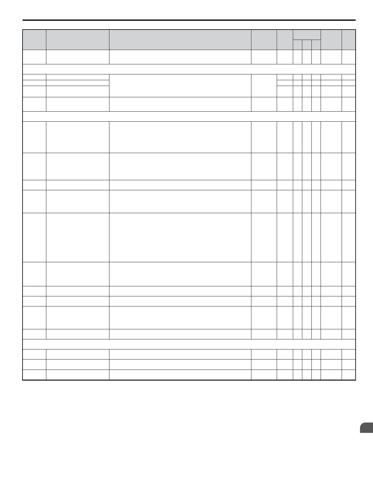
No. Name Description Range Def.
Control
Mode
Addr.
Hex
Pg.
V/f
OL
V
PM
d2-03
Master Speed Reference Lower
Limit
Sets the minimum frequency reference lower limit if the frequency reference is input
using an analog input. Set as a percentage of maximum output frequency (E1-04).
The higher of both values d2-01 and d2-03 will be the lower limit.
0.0 to 110.0 0.0% A A A 293 —
d3: Jump Frequency
Use d3 parameters to configure the drive Jump Frequency settings.
d3-01 Jump Frequency 1 d3-01 to d3-04 allow programming of three prohibited frequency reference points
for eliminating problems with resonant vibration of the motor / machine. This
feature does not eliminate the selected frequency values, but accelerates and
decelerates the motor through the prohibited bandwidth.The parameters must be
according to the rule; d3-01 ≥ d3-02 ≥ d3-03.
0.0 to 400.0
0.0 Hz A A A 294 —
d3-02 Jump Frequency 2 0.0 Hz A A A 295 —
d3-03 Jump Frequency 3 0.0 Hz A A A 296 —
d3-04 Jump Frequency Width
This parameter sets the dead-band width around each selected prohibited frequency
reference point. The bandwidth becomes the designated Jump frequency, plus or
minus d3-04.
0.0 to 20.0 1.0 Hz A A A 297 —
d4: Frequency Reference Hold
Use d4 parameters to configure the drive frequency reference hold function.
d4-01
Frequency Reference Hold Function
Selection
This parameter is used to hold the last frequency reference in U1-01 (d1-01) when
power is removed.
0: Disabled
1: Enabled
This function is available when the multi-function inputs “accel/decel ramp hold”
or “up/down” commands are selected
(H1-oo = A or 10 and 11).
0, 1 0 A A A 298 —
d4-03 <22> Frequency Reference Bias Step (Up/
Down 2)
Sets the bias added to the frequency reference when the Up/Down 2 digital inputs
are set.
When set to 0.00 Hz, the bias value is increased or decreased according to d4-04.
When greater than 0.0 Hz, the bias value d4-03 is added or subtracted to/from the
frequency reference.
The acceleration or deceleration rate is ultimately determined by d4-04.
0.00 to
99.99Hz
0.00 Hz A A A 2AA —
d4-04 <22> Frequency Reference Accel/Decel
(Up/Down 2)
0: Adjusts the bias value according to the currently selected accel/decel time.
1: Adjusts the bias value by Accel/Decel Time 4 (C1-07 and C1-08).
0, 1 0 A A A 2AB —
d4-05 <22>
Frequency Reference Bias
Operation Mode Selection (Up/
Down 2)
0: Holds the bias value when Up/Down 2 reference is on or off.
1: When the Up 2 reference and Down 2 reference are both on or both off, the applied
bias becomes 0.
Currently selected accel/ decel. times are used.
Enabled only when d4-03 = 0.
0, 1 0 A A A 2AC —
d4-06
Frequency Reference Bias (Up/
Down 2)
The Up/Down 2 bias value is saved in d4-06 once the frequency reference is
adjusted.
It is limited by d4-08 and d4-09.
The bias can be set by the user, but will be disabled under the following conditions:
• When none of the digital inputs are assigned to Up2/Down2 commands.
• When the frequency reference source has been changed (including multi-step
speed).
• When both d4-03 = 0 and d4-05 = 1 and the Up 2 / Down 2 commands are both
on or both off.
• When the max output frequency E1-04 has changed.
-99.9 to
+100.0
0.0% A A A 2AD —
d4-07
<22>
Analog Frequency Reference
Fluctuation Limit (Up/Down 2)
• When during Up2/Down2 the frequency reference value from analog or pulse
input changes for more than the level set in d4-07, the bias value is hold and the
reference is changed to the new value.
• After the speed reaches the frequency reference the bias hold is released. (Works
with frequency reference from analog or pulse input only)
0.1 to +100.0 1.0% A A A 2AE —
d4-08
<22>
Frequency Reference Bias Upper
Limit (Up/Down 2)
Sets the upper limit for d4-06 in percent of the maximum output frequency E1-04. 0.1 to 100.0 0.0% A A A 2AF —
d4-09
<22>
Frequency Reference Bias Lower
Limit (Up/Down 2)
Sets the lower limit for d4-06 in percent of the maximum output frequency E1-04. -99.9 to 0.0 0.0% A A A 2B0 —
d4-10
Up/Down Frequency Reference
Limit Selection
Selects which value is used as frequency reference lower limit if the Up/Down
function is used.
0: The lower limit is determined by d2-02 or analog input (H3-02/10 = 0). The higher
of both values becomes the reference limit.
1: The lower limit is determined by d2-02.
0 or 1 0 A A A 2B6 —
d4-12 Stop Position Gain
Sets the gain used by the simple positioning stop function to fine adjust the position.
Refer to the V1000 Technical Manual for details.
0.50 to 2.55 1.00 A A A 2B8
d7: Offset Frequency
Use d7 parameters to set the offset frequency.
d7-01
<22>
Offset Frequency 1
Added to the frequency reference when the digital input “Frequency Offset 1” (H1-
oo = 44) is switched on.
-100.0 to
+100.0
0.0% A A A 2B2 —
d7-02 <22>
Offset Frequency 2
Added to the frequency reference when the digital input “Frequency Offset 2” (H1-
oo = 45) is switched on.
-100.0 to
+100.0
0.0% A A A 2B3 —
d7-03 <22>
Offset Frequency 3
Added to the frequency reference when the digital input “Frequency Offset 3” (H1-
oo = 46) is switched on.
-100.0 to
+100.0
0.0% A A A 2B4 —
<11> Default setting value is dependent on parameter o1-03, Digital Operator Display Selection.
<19> Range upper limit is dependent on parameters E1-04, Maximum Output Frequency, and d2-01, Frequency Reference Upper Limit.
<22> Parameter can be changed during run.
B.2 Parameter Table
YASKAWA ELECTRIC SIEP C710606 18A YASKAWA AC Drive – V1000 Technical Manual (Preliminary)
301
B
Parameter List

 Loading...


