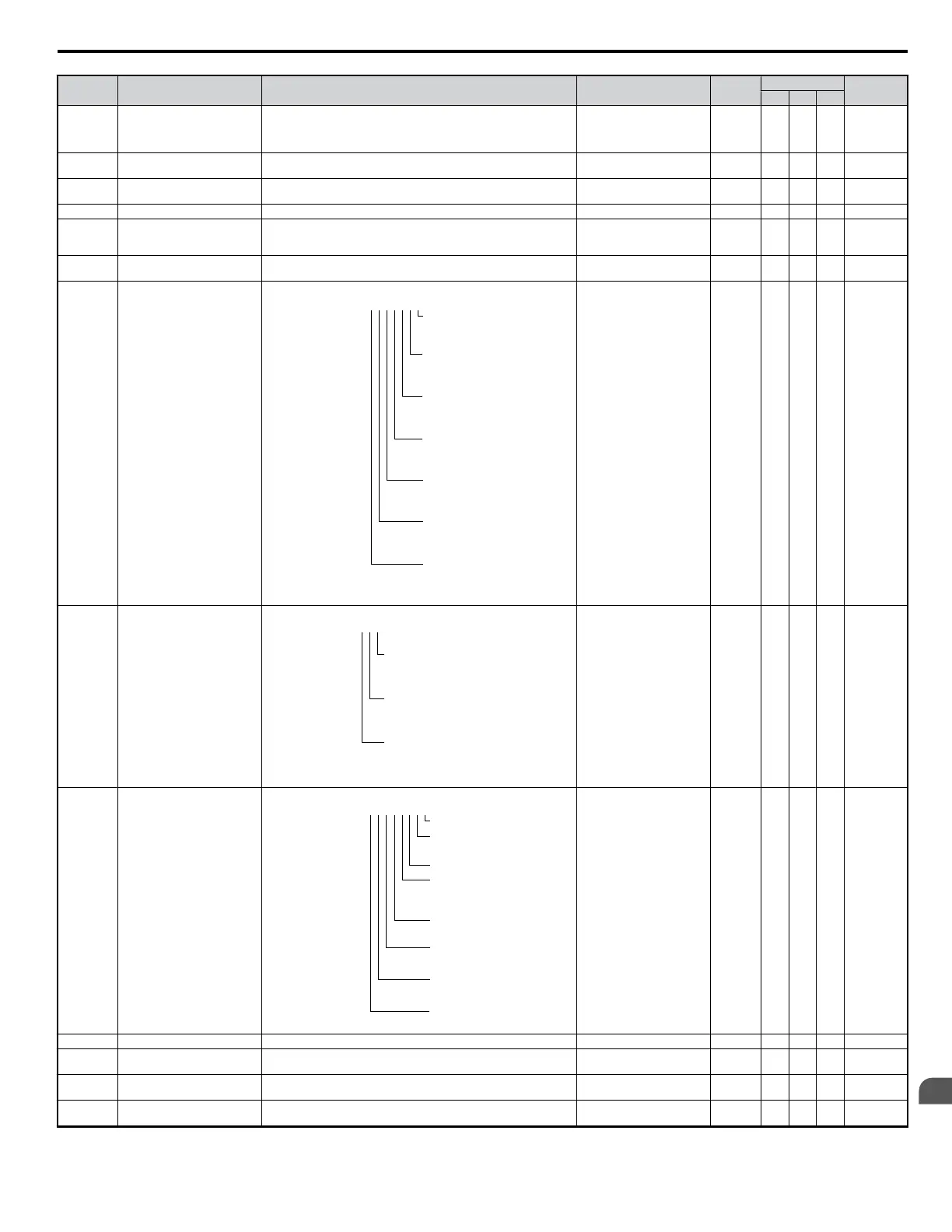
No. Name Description Analog Output Level Unit
Control Mode
Addr. Hex
V/f OLV PM
U1-04 Control Mode
Control method set in A1-02.
0: V/f without PG
2: Open Loop Vector (OLV)
5: PM Open Loop Vector (PM)
No output signal available – A A A 43
U1-05 Motor Speed
Displays the motor speed feedback.
Display units are determined by o1-03.
10 V: Maximum speed 0.01Hz – A A 44
U1-06 Output Voltage Reference Displays the output voltage.
10 V: 200 Vrms
(400 Vrms)
0.1 V A A A 45
U1-07 DC Bus Voltage Displays the DC bus voltage. 10 V: 400 V (800 V) 1 V A A A 46
U1-08 Output Power Displays the output voltage (this value is determined internally).
10 V: Drive capacity (kW)
(max. motor capacity
allowed)
<27> A A A 47
U1-09 Torque Reference
Monitor of internal torque reference value for Open Loop Vector (OLV)
control
10 V: Motor rated torque – – A –
U1-10 Input Terminal Status
Displays the input terminal status.
U1-09
=
0 0 0 0 0 0 0
1: FWD run
command
(terminal S1
enabled)
1: REV run
command
(terminal S2
enabled)
1: Multi-Function
Digital
Input 1 (terminal
S3 enabled)
1: Multi-Function
Digital
Input 2 (terminal
S4 enabled)
1: Multi-Function
Digital
Input 3 (terminal
S5 enabled)
1: Multi-Function
Digital
Input 4 (terminal
S6 enabled)
1: Multi-Function
Digital
Input 5 (terminal
S7 enabled)
No output signal available – A A A 49
U1-11 Output Terminal Status
Displays the output terminal status.
U1-11
=
0 0 0
1: Multi-Function
Digital Output (fault)
(terminal MA/MB-MC)
1: Multi-Function
Digital Output 1
(terminal P1) enabled
1: Multi-Function
Digital Output 2
(terminal P2) enabled
No output signal available – A A A 4A
U1-12 Drive Status
Verifies the drive operation status.
U1-12
=
0 0 0 0 0 0 0 0
1: During run
1: During
zero-speed
1: During REV
1: During fault
reset
signal input
1: During speed
agree
1: Drive ready
1: During alarm
detection
1: During fault
detection
No output signal available – A A A 4B
U1-13 Terminal A1 Input Voltage Displays the analog input A1 input level. 100% when the input is 10 V 10 V: 100% 0.1% A A A 4E
U1-14 Terminal A2 Input Voltage
Displays the analog input A2 input level. 100% when the input is 10 V /
20 mA
10 V: 100% 0.1% A A A 4F
U1-16
Output Frequency after Soft
Start
Displays the output frequency including ramp times, S-curves. Units are
determined by o1-03.
10 V: Max frequency 0.01Hz A A A 53
U1-18 OPE Fault Parameter
Displays the parameter number for oPEoo or Err (operator error) where
the error occurred.
No output signal available – A A A 61
B.2 Parameter Table
YASKAWA ELECTRIC SIEP C710606 18A YASKAWA AC Drive – V1000 Technical Manual (Preliminary)
319
B
Parameter List

 Loading...


