No. Parameter Name Description Setting Range Default Setting
L1-02
Motor Overload
Protection Time
Sets the electronic thermal overload protection detection time in the motor
overload protection (OL1) function.
This setting rarely needs to be changed and should be set in accordance with the
overload tolerance of the motor.
0.1 to 5.0 1.0 min
Note: Executing C6-01 (Duty Cycle) changes motor parameters E2 and E4 including motor rated current to the values of the maximum applicable motor.
Digital Outputs (H2-01 through H2-03)
Setting Function Description
1F
Motor Overload
OL1 Alarm Warning (including OH3)
Closed = When OL1 function is at 90% of its trip point or greater.
Setting Procedure
1.
Set E2-01 (Motor Rated Current) and E4-01 (Motor 2 Rated Current) to the motor rated current.
Note: 1. Values set for the current become the base current for electronic thermal overload protection.
2. These values are automatically set by performing Auto-Tuning.
3. The E4-01 setting is not needed if not using motor 2.
2.
Set the proper motor protection level to L1-01.
The ability of the cooling fan to keep an induction motor cool varies by the speed control range. Protection characteristics of the electronic thermal
overload protection should be set accordingly. Refer to
Table 4.21 for motor types and overload tolerances.
NOTICE: When connecting multiple motors to one drive, disable the electronic overload protection of the drive (L1-01 = 0) and protect each motor with its own motor
thermal overload. Failure to comply could result in improper drive operation.
NOTICE: Inadequate motor protection could result in damage to the motor. Configure a motor thermal overload to disconnect main power to the drive when tripped.
When using a thermal relay, disable the motor protection function (L1-01 = “0”).
3.
Set the motor overcurrent alarm warning level.
When H2-01, H2-02, and H2-03 (Terminal MA, MB, and MC Function selection, Terminal P1 Function Selection, and Terminal P2 Function
Selection) are set to 1F motor overload (OL1 alarm warning), a motor overload alarm is enabled. If the electronic thermal value exceeds 90% of
the overload detection level, the set output terminal turns on.
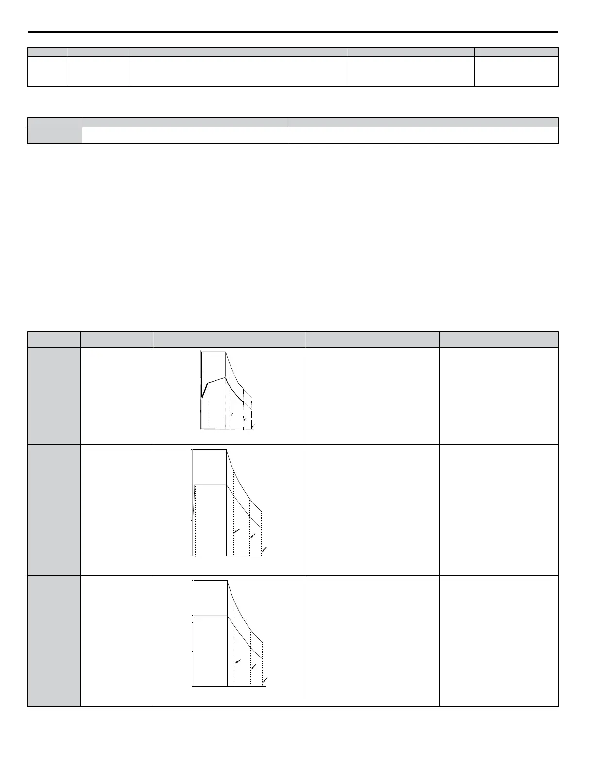
Table 4.21 Motor Type and Overload Tolerances
L1-01 Setting Motor Type Overload Tolerance Cooling Fan Capacity
Electrothermal Protection (100%
motor overload)
1
General-purpose motor
(standard motor)
100
150
90
60
50
Torque
(%)
60 seconds
Continuous
0 5 33 100
60Hz
120 167 200
(%)
Speed
C
B
Rated Speed = 100% Speed
A
General purpose motors are designed to operate
from line power. The most effective cooling
occurs when running at line power specifications.
Operating continuously at less than line
power frequency can trigger motor
overload protection (OL1). A fault is then
output and the motor will coast to stop.
2
Inverter Duty motor
(1:10)
100
150
55
50
(%)
60 seconds
Continuous
0
1 10
100
(60Hz)
120 167 200
(%)
Speed
A
D
B
Rated Speed = 100% Speed
Torque
Motor designed to effectively self-cool at speeds
as low as 6 Hz.
Continuous operation between 6 and 50/60
Hz.
3 Vector motor (1:100)
90
A
B
D
100
150
50
(%)
60 seconds
Continuous
0
1
100
(60Hz)
120 167 200
(%)
Speed
Rated Speed = 100% Speed
Torque
Motor capable of effective cooling at extremely
low speeds (0.6 Hz).
Continuous operation between 0.6 and 60
Hz.
4.6 Basic Drive Setup Adjustments
88
YASKAWA ELECTRIC SIEP C710606 18A YASKAWA AC Drive – V1000 Technical Manual (Preliminary)

 Loading...


