Cause Possible Solution
Motor insulation is damaged.
• Check the insulation resistance of the motor.
• Replace the motor.
A damaged motor cable is creating a short circuit.
• Check the motor cable.
• Remove the short circuit and turn the power back on.
•
Check the resistance between the cable and the ground terminal
.
• Replace the cable.
The leakage current at the drive output is too high.
• Reduce the carrier frequency.
• Reduce the amount of stray capacitance.
The drive started to run during Current Offset Fault or while
coasting to a stop.
• The value set exceeds the allowable setting range while the drive automatically adjusts the current offset (this happens only attempting
to restart a PM motor that is coasting to stop).
• Enable Speed Search at start (b3-01 = 1).
• Perform Speed Search 1 or 2 (H1-xx = 61 or 62) via one of the external terminals. Note: Speed Search 1 and 2 are the same when
using PM OLV.
Hardware problem. • Replace the drive.
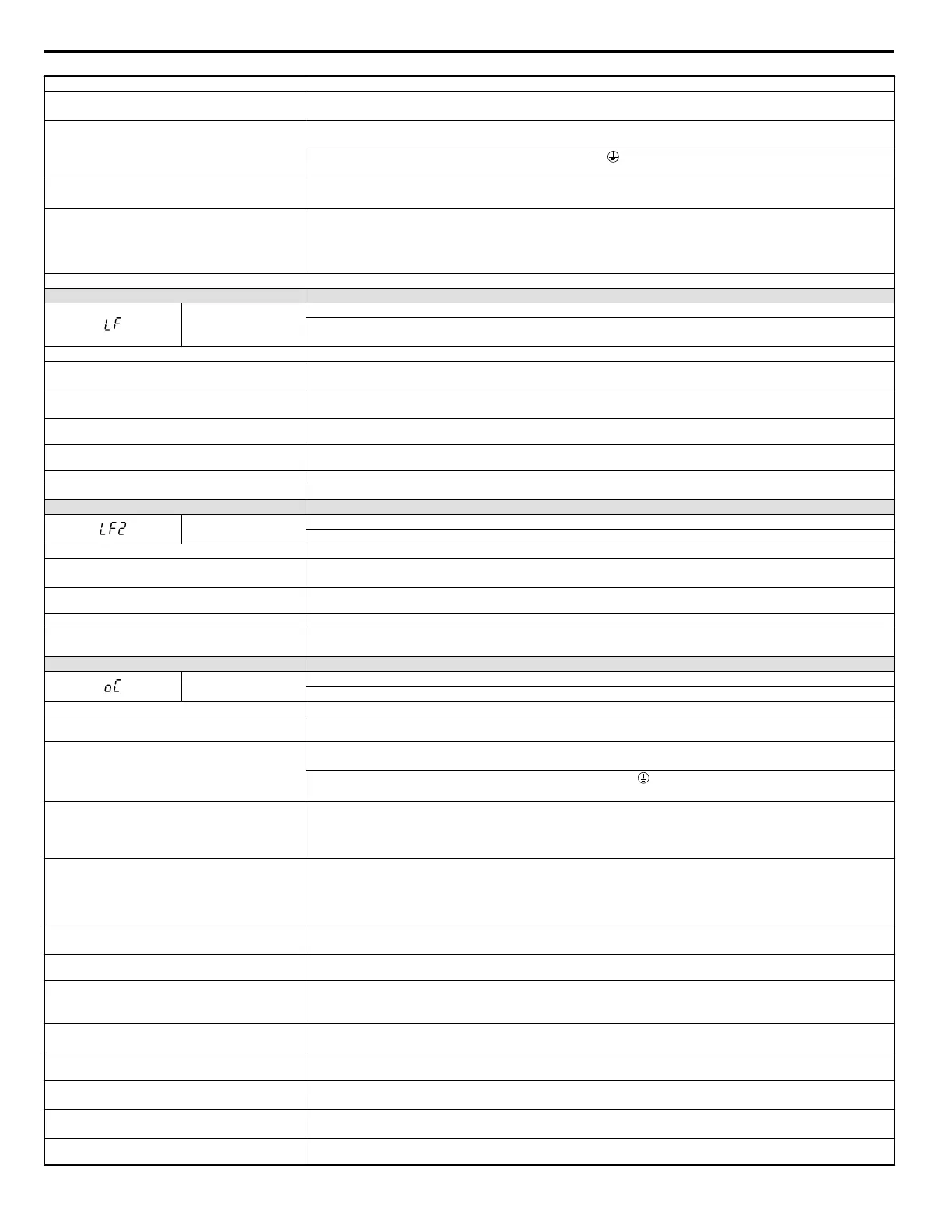
LED Operator Display Fault Name
LF
Output Phase Loss
• Phase loss on the output side of the drive.
• Phase Loss Detection is enabled when L8-07 is set to “1” or “2”.
Cause Possible Solution
The output cable is disconnected.
• Check for wiring errors and ensure the output cable is connected properly.
• Correct the wiring.
The motor winding is damaged.
• Check the resistance between motor lines.
• Replace the motor if the winding is damaged.
The output terminal is loose.
• Apply the tightening torque specified in this manual to fasten the terminals. Refer to Wire Size and Torque Specifications on page
46.
The motor being used is less than 5% of the drive rated
current.
Check the drive and motor capacities.
An output transistor is damaged. Replace the drive.
A single phase motor is being used. The drive being used cannot operate a single phase motor.
LED Operator Display Fault Name
LF2
Output current imbalance
One or more of the phases in the output current is lost.
Cause Possible Solution
Phase loss has occurred on the output side of the drive.
• Check for faulty wiring or poor connections on the output side of the drive.
• Correct the wiring.
Terminal wires on the output side of the drive are loose.
Apply the tightening torque specified in this manual to fasten the terminals. Refer to Wire Size and Torque Specifications on page
46.
No signal displays from the gate driver board. Replace the drive. Contact Yaskawa for assistance.
Motor impedance or motor phases are uneven.
• Measure the line-to-line resistance for each motor phase. Ensure all values are the same.
• Replace the motor. Contact Yaskawa for assistance.
LED Operator Display Fault Name
oC
Overcurrent
Drive sensors have detected an output current greater than the specified overcurrent level.
Cause Possible Solution
The motor has been damaged due to overheating or the motor
insulation is damaged.
Check the insulation resistance.
Replace the motor.
One of the motor cables has shorted out or there is a
grounding problem.
• Check the motor cables.
• Remove the short circuit and power the drive back up.
•
Check the resistance between the motor cables and the ground terminal
.
• Replace damaged cables.
The load is too heavy.
• Measure the current flowing into the motor.
• Replace the drive with a larger capacity unit if the current value exceeds the rated current of the drive.
• Determine if there is sudden fluctuation in the current level.
• Reduce the load to avoid sudden changes in the current level or switch to a larger drive.
The acceleration or deceleration times are too short.
Calculate the torque needed during acceleration relative to the load inertia and the specified acceleration time.
If the right amount of torque cannot be set, make the following changes:
• Increase the acceleration time (C1-01, -03, -05, -07)
• Increase the S-curve characteristics (C2-01 through C2-04)
• Increase the capacity of the drive.
The drive is attempting to operate a specialized motor or a
motor larger than the maximum size allowed.
• Check the motor capacity.
• Ensure that the rated capacity of the drive is greater than or equal to the capacity rating found on the motor nameplate.
Magnetic contactor (MC) on the output side of the drive has
turned on or off.
Set up the operation sequence so that the MC is not tripped while the drive is outputting current.
V/f setting is not operating as expected.
• Check the ratios between the voltage and frequency.
• Set parameter E1-04 through E1-10 appropriately. Set E3-04 through E3-10 when using a second motor.
• Lower the voltage if it is too high relative to the frequency.
Excessive torque compensation.
• Check the amount of torque compensation.
• Reduce the torque compensation gain (C4-01) until there is no speed loss and less current.
Drive fails to operate properly due to noise interference.
• Review the possible solutions provided for handling noise interference.
• Review the section on handling noise interference and check the control circuit lines, main circuit lines and ground wiring.
Overexcitation gain is set too high.
• Check if fault occurs simultaneously to overexcitation function operation.
• Consider motor flux saturation and reduce the value of n3-13 (Overexcitation Deceleration Gain).
Run command applied while motor was coasting.
• Enable Speed Search at start (b3-01 = “1”).
•
Program the Speed Search command input through one of the multi-function contact input terminals (H1-oo = “61” or “62”).
The wrong motor code has been entered for PM Open Loop
Vector (Yaskawa motors only).
Enter the correct motor code to E5-01 to indicate that a PM motor is connected.
6.4 Fault Detection
232
YASKAWA ELECTRIC SIEP C710606 18A YASKAWA AC Drive – V1000 Technical Manual (Preliminary)

 Loading...


