Cause Possible Solution
Motor has overheated.
• Check the size of the load, the accel/decel times and the cycle times.
• Decrease the load.
• Increase the acceleration and deceleration times (C1-01 through C1-08).
• Adjust the preset V/f pattern (E1-04 through E1-10). This will mainly involve reducing E1-08 and E1-10. Be careful not to lower
E1-08 and E1-10 excessively because this reduces load tolerance at low speeds
• Check the motor-rated current.
• Enter the motor-rated current as indicated on the motor nameplate (E2-01).
• Ensure the motor cooling system is operating normally.
• Repair or replace the motor cooling system.
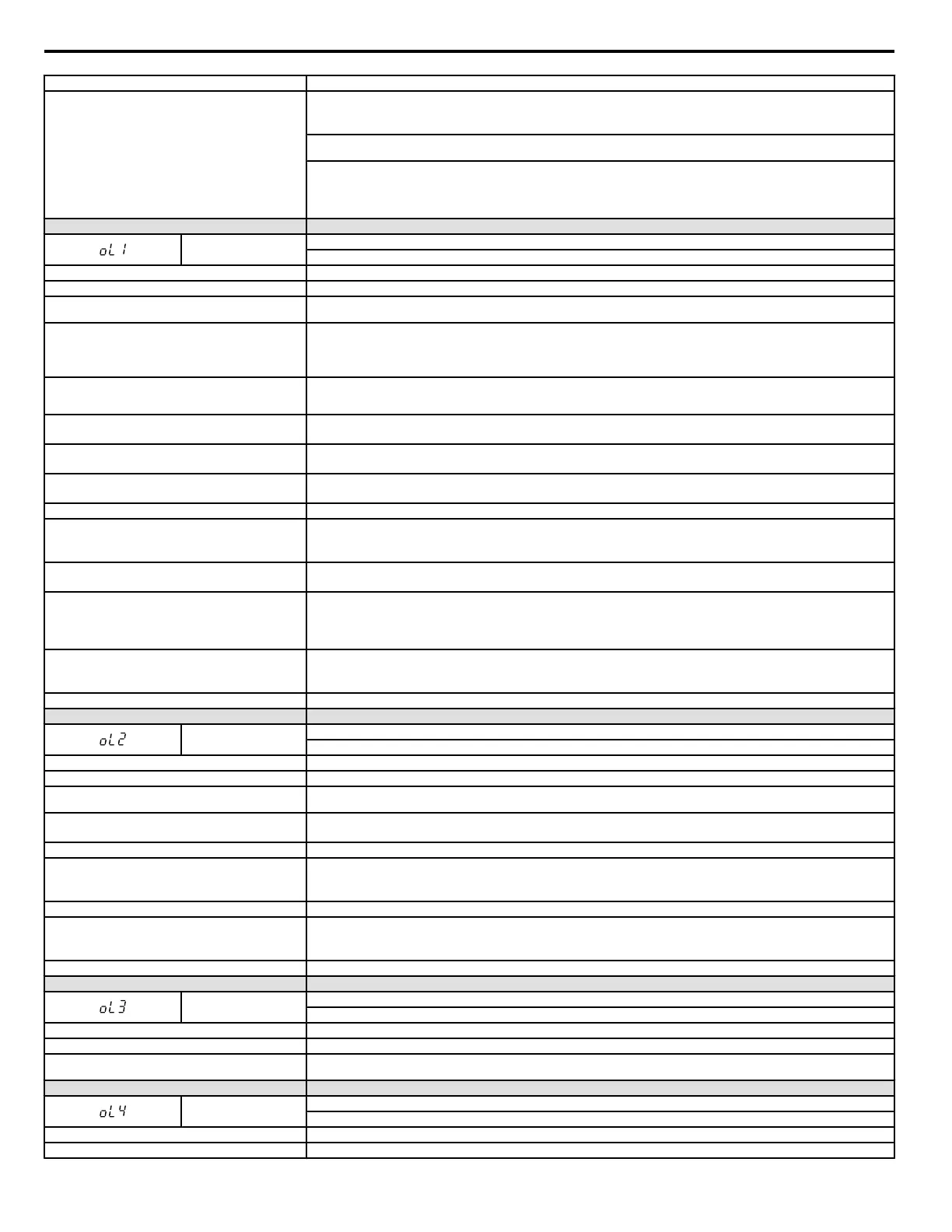
LED Operator Display Fault Name
oL1
Motor Overload
The electrothermal sensor tripped overload protection.
Cause Possible Solution
Load is too heavy. Reduce the load.
Cycle times are too short during acceleration and
deceleration.
Increase the acceleration and deceleration times (C1-01 through C1-08).
• Drive overloaded at low speeds.
• Overload may occur at low speeds when using a general-
purpose motor, even if operating within the rated current
limitation.
• Reduce the load.
• Increase the speed.
• If the drive is supposed to operate at low speeds, either increase the motor capacity or use a motor specifically designed to operate
with the drive.
Although a special type of motor is being used, the motor
protection selection is set for a general-purpose motor
(L1-01 = 1).
Set L1-01 = “2”.
Voltage is too high for the V/f characteristics.
• Adjust the user set V/f patterns (E1-04 through E1-10). Parameters E1-08 and E1-10 may need to be reduced.
• If E1-08 and E1-10 are set too high, there may be very little load tolerance at low speed.
The wrong motor-rated current is set to E2-01.
• Check the motor-rated current.
• Enter the value written on the motor nameplate to parameter E2-01.
The maximum frequency for the drive input power is set too
low.
• Check the rated frequency indicated on the motor nameplate.
• Enter the rated frequency to E1-06 (Base Frequency).
Multiple motors are running off the same drive. Disable the Motor Protection function (L1-01 = “0”) and install a thermal relay to each motor.
The electrical thermal protection characteristics and motor
overload characteristics do not match.
• Check the motor characteristics.
• Correct the value set to L1-01 (Motor Protection Function).
• Install an external thermal relay.
The electrical thermal relay is operating at the wrong level.
• Check the current rating listed on the motor nameplate.
• Check the value set for the motor-rated current (E2-01).
Overexcitation current is enabled.
• Overexcitation is a potential serious danger to the motor.
• Reduce the excitation deceleration gain (n3-13).
• Set L3-04 (Stall Prevention during Deceleration) to a value other than 4.
• Disable overexcitation (n3-23 = “0”).
Speed Search related parameters are not set to the proper
values.
• Check values set to Speed Search related parameters.
• Adjust the Speed Search current and Speed Search deceleration times (b3-02 and b3-03 respectively).
• After Auto-Tuning, enable Speed Estimation Type Search (b3-24 = “1”).
Output current fluctuation due to input phase loss Check the power supply for phase loss.
LED Operator Display Fault Name
oL2
Drive Overload
The thermal sensor of the drive triggered overload protection.
Cause Possible Solution
Load is too heavy. Reduce the load.
Cycle times are too short during acceleration and
deceleration.
Increase the settings for the acceleration and deceleration times (C1-01 through C1-08).
Voltage is too high for the V/f characteristics.
• Adjust the preset V/f pattern (E1-04 through E1-10). This will mainly involve reducing E1-08 and E1-10.
• Be careful not to lower E1-08 and E1-10 excessively because this reduces load tolerance at low speeds.
Drive capacity is too small. Replace the drive with a larger model.
Overload occurred when operating at low speeds.
• Reduce the load when operating at low speeds.
• Replace the drive with a model that is one frame size larger.
• Lower the carrier frequency (C6-02).
Excessive torque compensation. Reduce the torque compensation gain (C4-01) until there is no speed loss but less current.
Speed Search related parameters are not set correctly.
• Check the settings for all Speed Search related parameters.
• Adjust the current used during Speed Search and the Speed Search deceleration time (b3-03 and b3-02 respectively).
• After Auto-Tuning the drive, enable the Speed Search Estimation Type (b3-24 = “1”).
Output current fluctuation due to input phase loss Check the power supply for phase loss.
LED Operator Display Fault Name
oL3
Overtorque Detection 1
The current has exceeded the value set for torque detection (L6-02) for longer than the allowable time (L6-03).
Cause Possible Solution
Parameter settings are not appropriate for the type of load. Check the settings of parameters L6-02 and L6-03.
There is a fault on the machine side (e.g., the machine is
locked up).
Check the status of the load. Remove the cause of the fault.
LED Operator Display Fault Name
oL4
Overtorque Detection 2
The current has exceeded the value set for Overtorque Detection 2 (L6-05) for longer than the allowable time (L6-06).
Cause Possible Solution
Parameter settings are not appropriate for the type of load. Check the settings of parameters L6-05 and L6-06.
6.4 Fault Detection
234
YASKAWA ELECTRIC SIEP C710606 18A YASKAWA AC Drive – V1000 Technical Manual (Preliminary)

 Loading...


