0 V 10 V
Gain = 100 %
Output
Frequency
Bias = 0 %
Figure 5.60 Output Frequency as Commanded via Analog Input
If a different span of analog input signal is desirable, it will be necessary to adjust the gain, the bias, or both to allow the analog input level to generate
the desired frequency command. Adjustment of the gain setting will change the frequency reference that is equivalent to the maximum analog input (10
Vdc). If, for instance, the gain is increased to 200%, then 10 Vdc will be equivalent to a 200% frequency reference and 5 Vac will be equivalent to a 100%
frequency reference. Since the drive output is limited by the maximum frequency parameter (E1-04), 0 to 5 Vdc will now be equivalent to 0 - 100%
frequency reference span.
10 V5 V
0 V
Gain = 200 %
100 %
Output
Frequency
Bias = 0 %
E1-04
Figure 5.61 Output Frequency Using Analog Input with Increased Gain
Adjustment of the bias setting will likewise adjust the frequency reference that is equivalent to the minimum analog input level (0 Vdc). If, for instance,
the bias is set to -25%, then 0 Vdc will be equivalent to a -25% frequency reference. Since the minimum frequency reference is 0% an analog input of
2.5 to 10 Vdc will now be equivalent to 0 - 100% speed command span.
2.0 V
0 V
10 V
Gain = 100 %
Output
Frequency
Bias = 25 %
Analog Input Signal
Figure 5.62 Output Frequency Using Analog Input with Reduced Gain
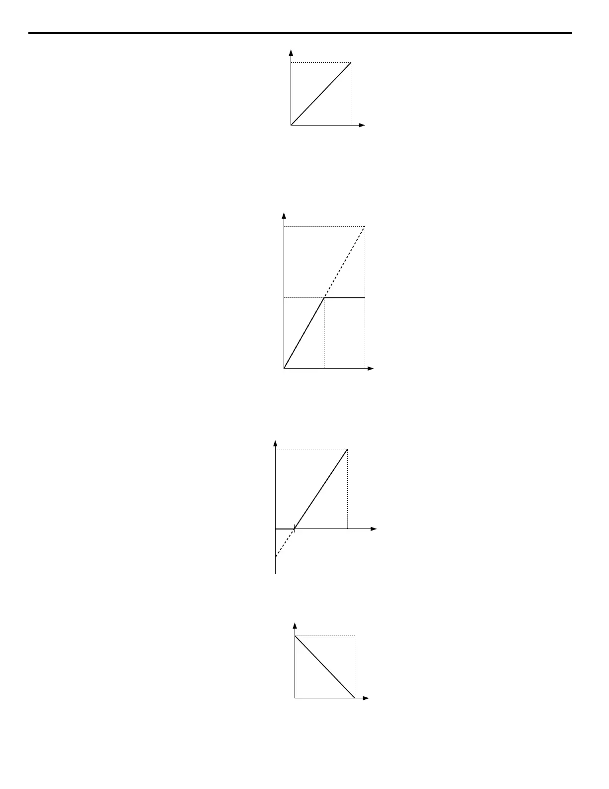
As a further example, for an inverse-acting frequency reference, set the bias= 100% and the gain = 0%. The minimum analog input level (0 Vdc) will
produce a 100% frequency reference and the maximum analog input level (10 Vdc) will produce a 0% frequency reference.
0 V 10 V
Gain = 0 %
Bias = 100 %
Output
Frequency
Figure 5.63 Output Frequency with Inverted Gain and Bias Settings
5.7 H: Terminal Functions
180
YASKAWA ELECTRIC SIEP C710606 18A YASKAWA AC Drive – V1000 Technical Manual (Preliminary)

 Loading...


