EasyManuals Logo

YASKAWA V1000 Series Technical Manual

YASKAWA V1000 Series
372 pages
To Next Page IconTo Next Page
To Previous Page IconTo Previous Page
Page #35 background imageLoading...
Page #35 background image
WARNING! When the application preset function is executed (or A1-06 is set to any value other than 0) the drive I/O terminal functions change. This may cause unexpected
operation and potential damage to equipment or injury.
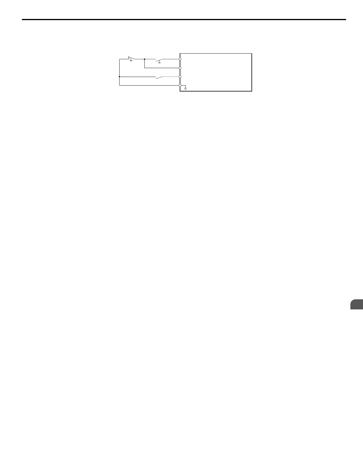
Figure 3.2 illustrates an example of a 3-wire sequence.
Drive
Sequence input common
Run relay (N.O.)
Stop relay (N.C.)
Run command (run on momentary close)
Stop command (stop on momentary open)
Foward/reverse command
(multi-function input: H1-05 = 0)
S1
S2
S5
SC
Figure 3.2 3-Wire Sequence
3.2 Standard Connection Diagram
YASKAWA ELECTRIC SIEP C710606 18A YASKAWA AC Drive – V1000 Technical Manual (Preliminary)
35
3
Electrical Installation

Table of Contents

Other manuals for YASKAWA V1000 Series

Questions and Answers:

Question and Answer IconNeed help?

Do you have a question about the YASKAWA V1000 Series and is the answer not in the manual?

YASKAWA V1000 Series Specifications

General IconGeneral
ModelV1000 Series
SeriesV1000
Output Frequency0.1 to 400 Hz
Overload Capacity150% for 60 seconds
TypeAC Drive
Control MethodV/f Control
Input Voltage200-240V, 380-480V
Output Voltage0 to Input Voltage
Power Range0.1 to 18.5 kW
Horsepower0.2 to 25 HP
Protection FeaturesOvercurrent, Overvoltage, Undervoltage, Overheating, Short Circuit, Ground Fault
Communication InterfacesModbus RTU
EnclosureIP20
Ambient Temperature-10 to +50°C
Storage Temperature-20 to +60°C
Humidity5 to 95% RH (non-condensing)
Cooling MethodFan Cooled

Related product manuals