n
Setting Notes
• If stalling occurs with L3-02 set to its default value when using a motor that is relatively small compared to the drive, try lowering L3-02.
• When operating the motor within a constant output range, L3-02 is automatically reduced to prevent speed loss. L3-03 limits the degree to which L3-02
is reduced while attempting to maintain constant output.
• Set as a percentage of the drive rated current.
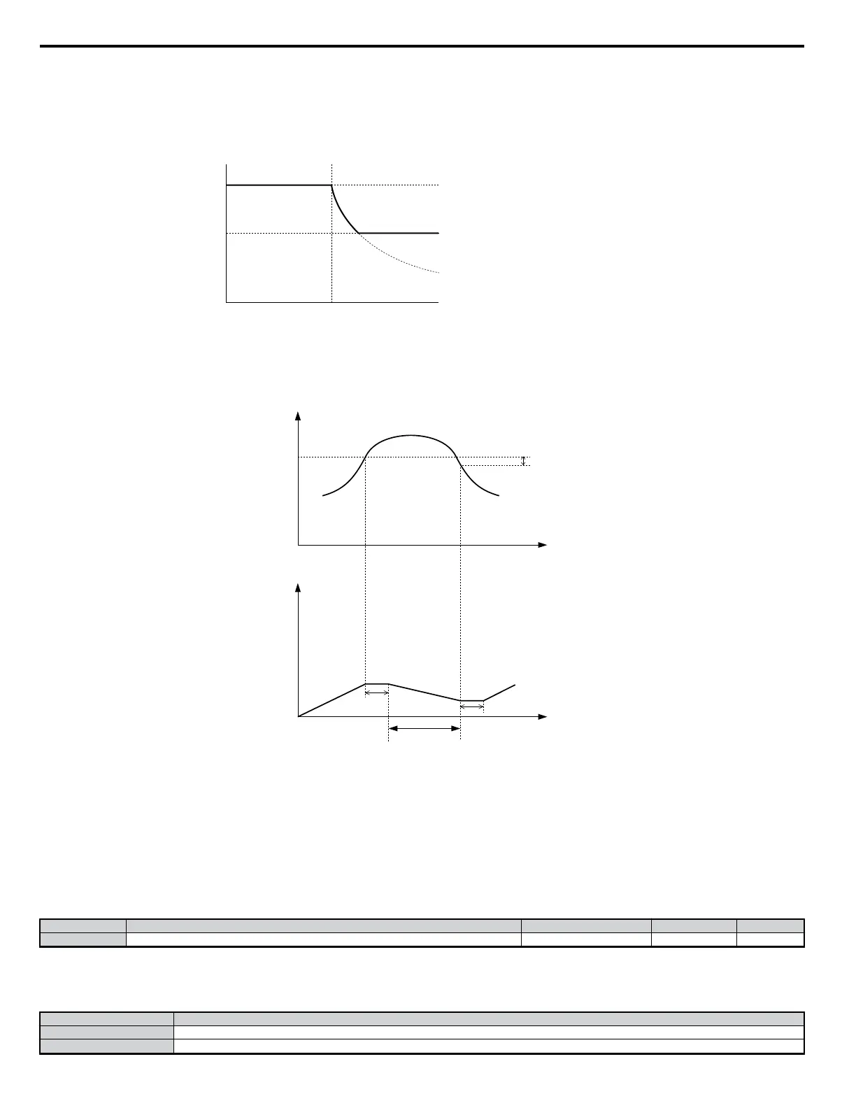
Stall Prevention level during acceleration
Output Frequency
L3-02 × L3-03
E1-06
base frequency (FA)
L3-02
Figure 5.74 Stall Prevention Level and Limit during Acceleration
• If operation exceeds the Stall Prevention level set to L3-02 for more than 100 ms when using PM Open Loop Vector Control, then the drive will respond
by briefly decelerating for the time specified in L3-22. Acceleration will resume once the Stall Prevention level falls below L3-02 for 100 ms.
15%
L3-06
Time
Time
Motor Current
Motor Current
decelerates according
to L3-22
100 ms
100 ms
n
L3-22: Deceleration Time at Stall Prevention during Acceleration
Sets the brief deceleration time for when stalling occurs while accelerating a PM motor. When set to 0, this function is disabled and the drive will decelerate
at a normal rate when stalling occurs.
Note: The function is available only in Open Loop Vector Control Mode for PM motors.
• L3-01 = 2
Ignores the acceleration time that has been set and instead accelerates as quickly as possible without the motor stalling.
Accelerates at the optimal level without exceeding the Stall Prevention level set for acceleration (L3-02).
n
L3-04: Stall Prevention Selection during Deceleration
No. Name Setting Range Default Page
L3-04 Stall Prevention Selection during Deceleration 0 to 4 1 −
Stall Prevention during deceleration keeps the deceleration rate smooth while keeping the voltage in the DC bus from tripping an OV fault.
Detailed Description
Settings for L3-04 and their meanings appear in the table below.
Setting Description
0 Disabled (drive decelerates at the active deceleration rate)
1
*
General Purpose (no braking resistor)
5.8 L: Protection Functions
192
YASKAWA ELECTRIC SIEP C710606 18A YASKAWA AC Drive – V1000 Technical Manual (Preliminary)

 Loading...


