Introduction Configuring LAG
Software Reference for SwitchBlade x3100 Series Switches (Layer Two Switching)
4-26
4.3.2.4 Feature Interactions
UFO mode is set on a VLAN basis. However, on the SBx3112, a VLAN can have only one associated upstream
port. As a result, the two features cannot work together; the VLANs associated with a LAG must not be in
UFO mode.
4.3.2.5 Configuration Procedure - Creating a LAG
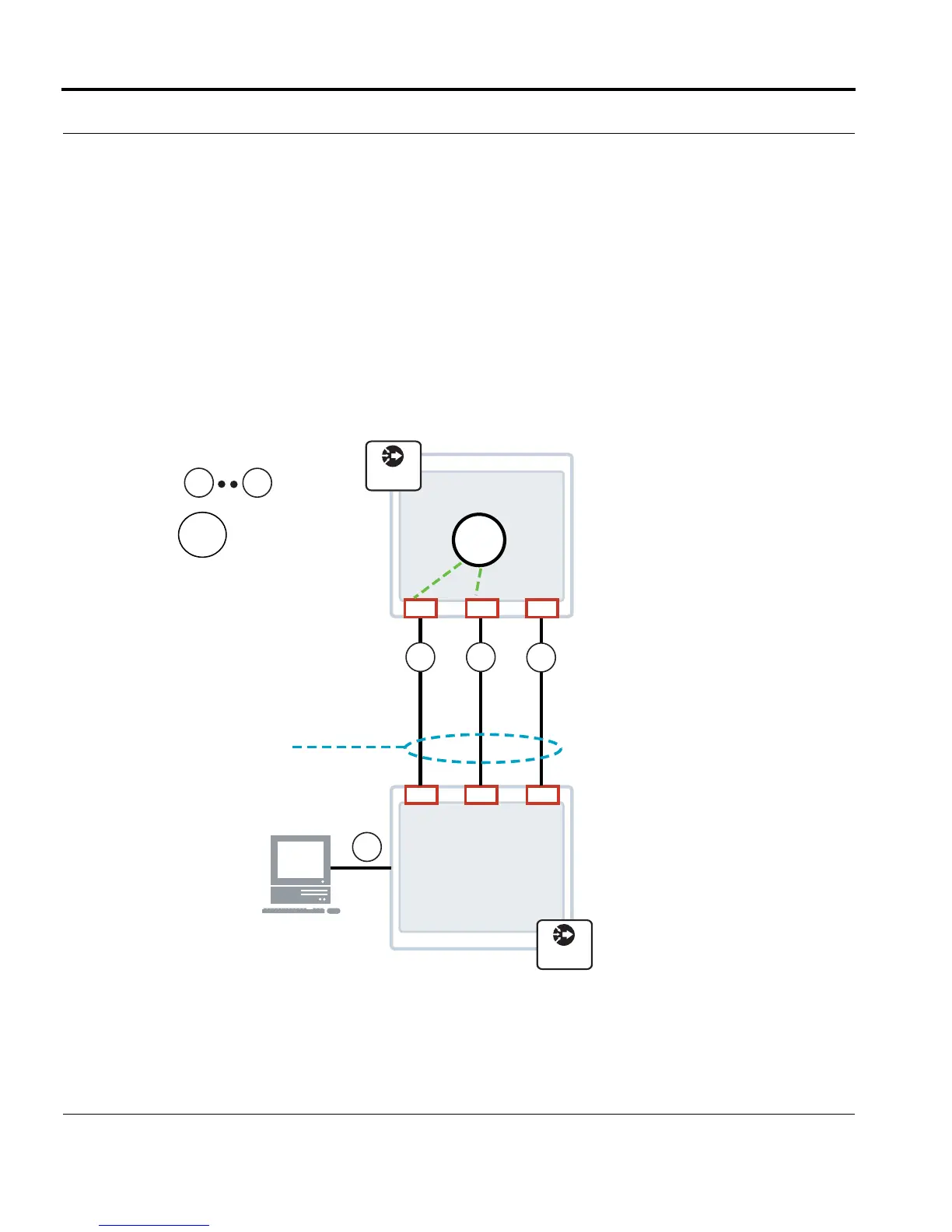
Figure 4-2 demonstrates the use of a LAG to aggregate three 1 Gbps physical links into a single 3 Gbps logical
link between two SBx3112 systems. The links being aggregated span two different line cards of the SBx3112.
Links 1 and 2 already share provisioning (including same VLAN 1500) before the LAG is created. However,
before Link 3 can be added to the LAG, it’s provisioning attributes must be modified to match those of links 1
and 2.
FIGURE 4-2 Sample Cross-Card LAG Configuration
SBx3112
= Links
1
0.9 3.00.8
1500
= VLAN
7.67.5 7.7
SBx3100
CPE
1 Gbps1 Gbps 1 Gbps
LAG
(3 Gbps)
1 2
3
4
1500
4
SBx3112
SBx3100

 Loading...


