Introduction Configuring LLDP
Software Reference for SwitchBlade x3100 Series Switches (Network Management)
7-74
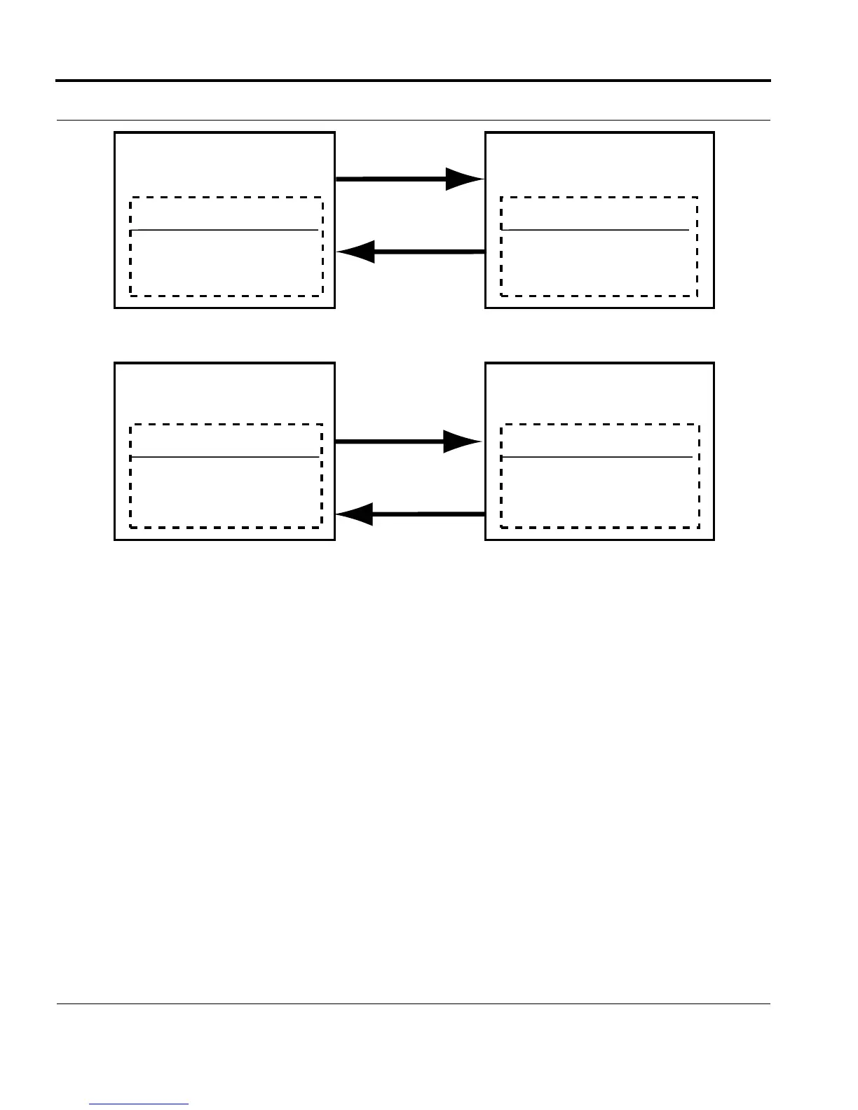
FIGURE 7-11 Effect of Disabling LLDP on a Single Interface
The top of Figure 7-11 shows that with LLDP enabled and running on both switches for both directions, both
switches discover each other and populate their tables with the neighbor’s data for that interface. The bottom
of the figure shows that with LLDP disabled on switch A, the following occurs:
• Switch A stops transmitting LLDP packets describing itself to Switch B, so the data for Switch A ages out in
the Switch B table. Switch B is now not LLDP aware of Switch A anymore.
• Switch A does not accept and discards the packets that are sent by Switch B, so Switch A is not LLDP aware
of Switch B.
7.4.2 Configuring LLDP
7.4.2.1 Default Configuration
When an SBx3112 switch is initially booted up, LLDP will be configured as follows:
• For all interfaces, LLDP is disabled (MODE=OFF)
lldp_port
XX
X
LLDP Neighbor Table
LLDP enabled on port A1
Switch A
Port Data
A1 Switch B Data
LLDP Neighbor Table
LLDP enabled on port A1
Switch B
Port Data
B5 Switch A Data
Port A1
Port B5
Port A1
Port B5
LLDP Neighbor Table
LLDP disabled
disabled on port A1
Switch A
Port Data
Empty for for B5Empty for for A1
LLDP Neighbor Table
LLDP enabled on port A1
Switch B
Port Data

 Loading...


