Commissioning
8
CCD CAM 100 – Installation and Operating Manual 101/198
If one material strip is outside the permitted range (e.g. outside
the measuring range), it is represented red in the display. A
black arrow indicates the direction in which the material strip
should be moved.
2. Move the material strips until both strips are in a permitted
position. The strips are represented green in the display.
3. Press the button to complete the adjustment step.
The screen display changes to the next step.
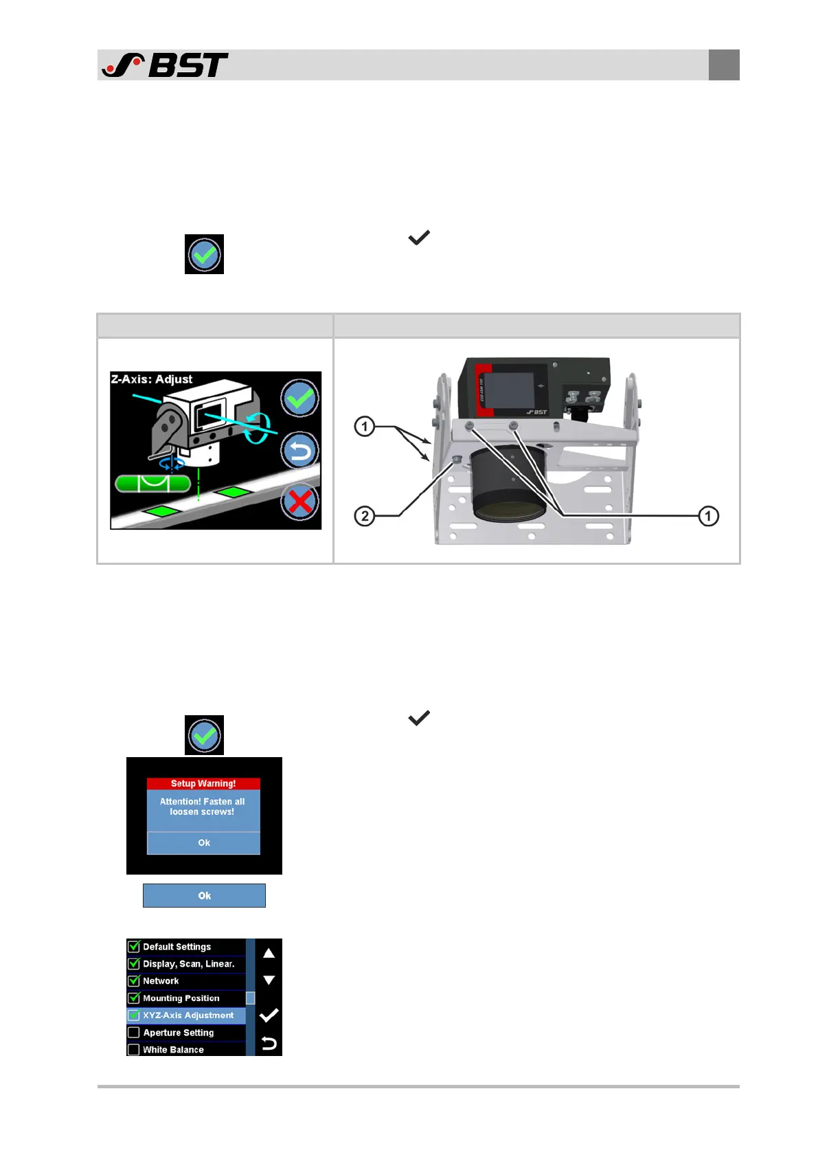
Aligning the CCD camera
Display Screen Mechanical Setting
1. Loosen the four locking screws ① of the mounting bracket.
Two screws are each located on the front and the back side of
the mounting bracket.
2. Swivel the CCD camera around the Z axis by turning the adjust-
ing screw ② until it is positioned precisely perpendicular to
the web running level. When aligned correctly, the color of the
spirit-level symbol in the display changes from red to green.
3. Press the button to complete the adjustment step.
A warning message appears on the screen. It prompts you to
tighten all locking screws after finishing the camera alignment.
4. Tighten all locking screws of the mounting bracket and of the
zoom lens which have been loosened.
5. Press the OK button.
The alignment of the CCD camera is finished.
The Normal Setup menu appears in the display.
A green checkmark is displayed in front of the XYZ-Axis Adjust-
ment menu item. It indicates that the alignment of the CCD
camera has been carried out successfully.
 Loading...
