DEQX User Manual
JUMPER SETTINGS
Table 5 and Table 6 list the full scale input or output voltage for each jumper position.
The highlighted row indicates the default setting as shipped from the factory.
Table 5. Analog input sensitivity jumper settings
Full scale single ended input
Table 6. Analog output gain jumper settings
Full scale balanced output
(typ.)
Full scale single ended
output (typ.)
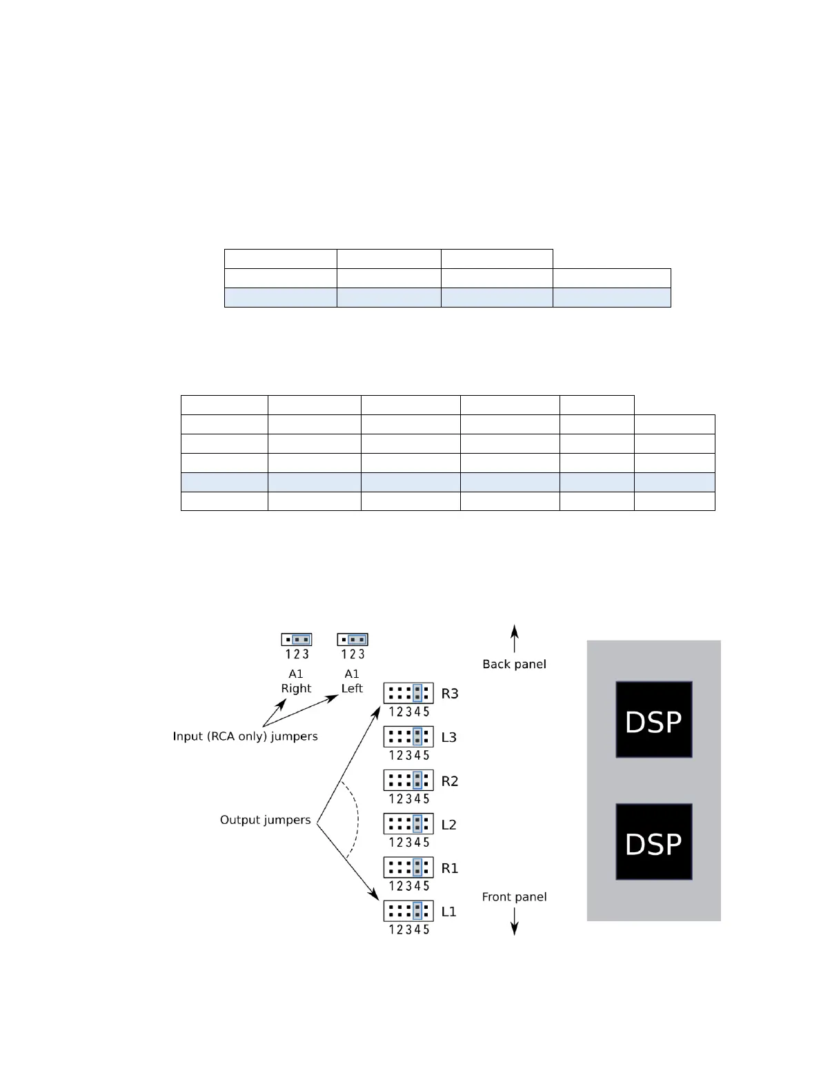
JUMPER LOCATIONS
View the main circuit board from above and with the front panel of the unit toward you.
The jumpers are located to the left of the DSP daughterboard as shown in the diagram
below. The jumper positions on this diagram match those in Table 5 and Table 6 above.