DEQX User Manual
13.5.4 Viewing correction and limit filters
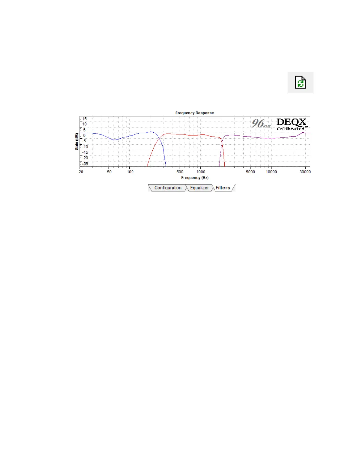
To view the complete set of correction and limit filters, go to the Filters
tab and click the Refresh Filters button. In the example below, the lower
crossover has been set with 96 dB/octave limit filters and the higher
crossover with 300 dB/octave crossover slopes.
13.5.5 Upload to DEQX
After completing initial configuration, click Save All to DEQX. If implementing a 2-way
active speaker with subwoofers, proceed to perform room measurement, subwoofer
integration, and room correction as described in Chapters 10 through 12. If
implementing a 3-way speaker using the “Bi-amp with optional stereo subwoofers”
configuration mode, you will need to perform an additional configuration step to set
delays and levels (see below), after which room measurement and correction can be
performed.
13.5.6 Woofer-mid time alignment and level adjustment (three-way)
A three-way speaker using the “bi-amp with optional stereo subwoofers” speaker
configuration mode (Figure 6 on page 108) requires a separate level and delay
adjustment step. (In tri-amp mode, the relative level and delay of the woofer is
automatically set. This does not happen automatically when the woofer is measured
and calibrated separately.)
One effective way to make this adjustment is to complete configuration of the DEQX,
then run a room measurement. To improve the quality of this measurement, locate the
microphone 1 to 2 meters (3 to 6 feet) from the speaker and an equal distance from the
woofer and midrange.
Open this measurement in a data viewer and determine the relative levels and time
delays of the woofer and midrange, then set these levels and delays in the
configuration. Apart from microphone location, the procedure is essentially the same as
described in Chapter 11.