DEQX User Manual
7.4 SET THE CORRECTION FREQUENCY LIMITS
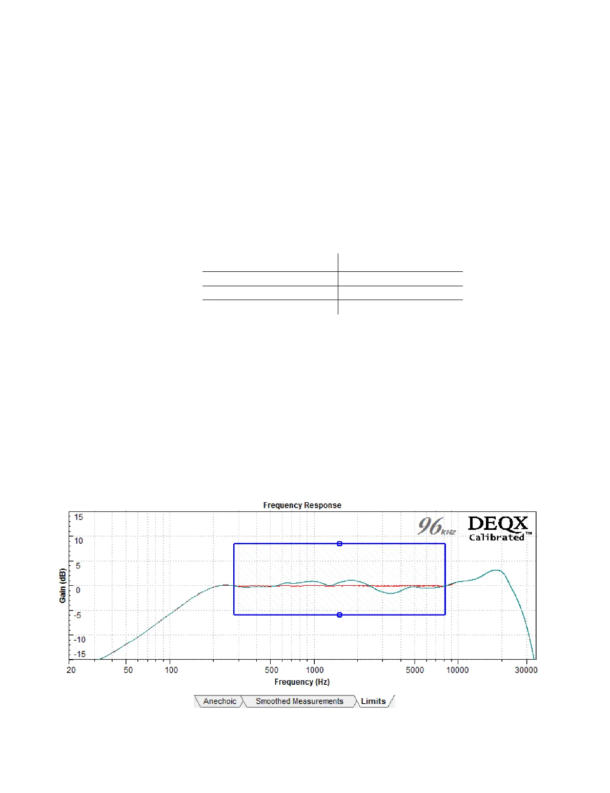
Screen 3 / Limits tab. The blue rectangle on this tab sets the correction frequency
region and its cut and boost limits. The rectangle can be altered by clicking and
dragging on any of its edges. The predicted response (shown in red by default) will
change as the edges are moved.
x The left edge sets the lower frequency limit . Set this edge using Table 3 below as a
guide. Do not set the limit any lower than suggested in Table 3, as your calibration will
be incorrect if you do so.
Table 3. Lower frequency limit vs window length
x The right edge sets the upper frequency limit. Set it at or close to a frequency where
the plot crosses the 𝟢 dB line (in order to minimize abrupt changes in the correction
filter). A frequency between 5 and 10 kHz is often a good choice, as this allows the
tweeter to keep its own character at the extreme high frequencies while providing
accurate calibration across the midrange and most of the treble. Alternatively, set
the upper frequency near or above 20 kHz to fully correct the speaker’s response.
x The top and bottom edges set the maximum cut and boost (respectively) of the
correction filter. Move the top edge down toward 𝟢 dB to limit the amount of cut,
and move the bottom edge up toward 𝟢 dB to limit the amount of boost. When the
edge intersects the plot, the amount of cut or boost will be reduced and the
predicted response plot will change accordingly.