Chapter 2. Installation and Connectivity
2.7 CONTROL/DATA INTERFACES
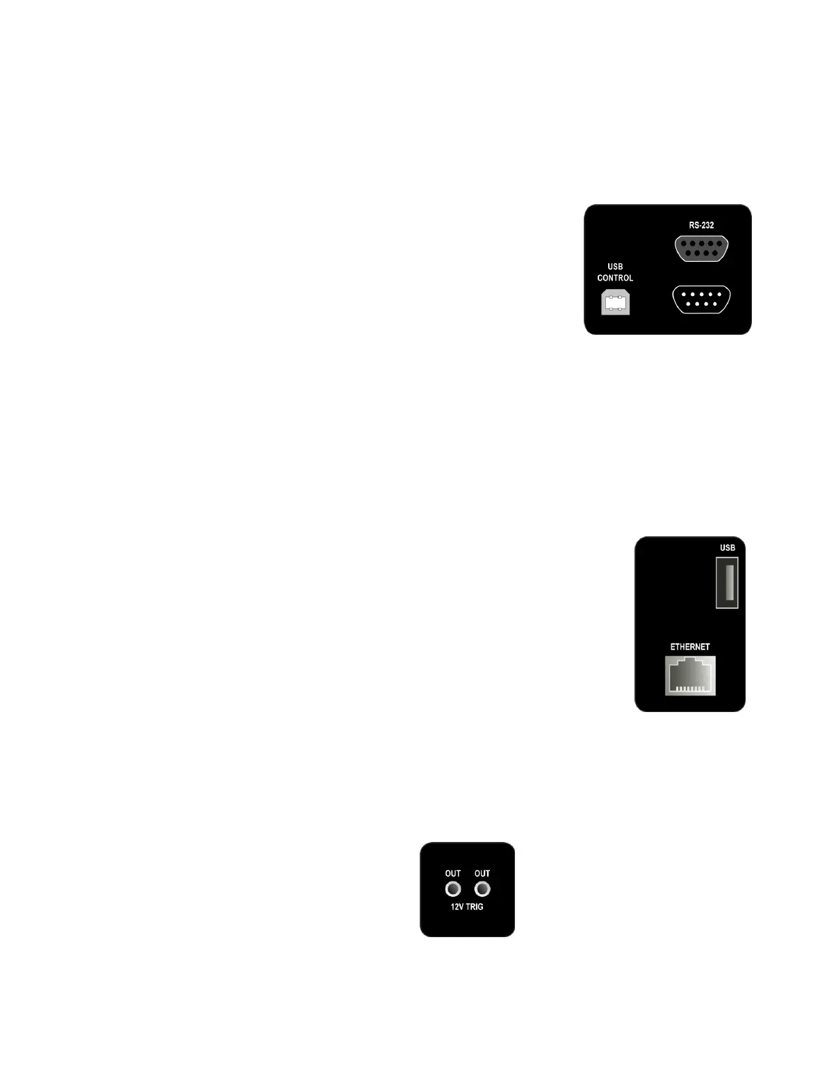
The rear panel contains a number of control/data interfaces.
USB Control
The USB Control socket is located at the lower left of
the rear panel (when facing the rear panel). Use the
supplied USB cable to connect the DEQX to your
computer when running DEQX-Cal.
(For PreMATE+ and HDP-5 owners: when the DEQX
detects communication from the DEQX-Cal software
over USB, the LCD touchscreen will be disabled and
will power off after a time.)
RS-232
The top RS-232 port is an input control port. It is used when the DEQX is a slave
unit in a multi-DEQX system (Chapter 14). It can also be used to control the DEQX
from certain home automation systems (e.g. Crestron). In the latter case, contact
DEQX directly for details of the RS-232 control protocol.
The bottom RS-232 port is an output control port, used in master-slave
configurations with multiple DEQX units (see Chapter 14).
Ethernet (PreMATE+ and HDP-5 only)
The Ethernet port is used for networked streaming audio.
See Appendix C for full information on this feature.
USB (PreMATE+ and HDP-5 only)
The USB (Type A) port is used for firmware updates of the
touchscreen display CPU.
2.8 TRIGGER OUTPUT
The PreMATE+ and HDP-5 have two 3.5 mm trigger sockets on the rear panel. These
outputs provide a 12 V DC trigger shortly after the DEQX is taken out of standby, and
can be used to turn on external amplification.
Both sockets are identical. There are two sockets provided for convenience, as the
DEQX unit often drives multiple amplifiers.