16.3.2 Connectors and indicators on the I/O panel
16.3.2.1 I/O panel connectors
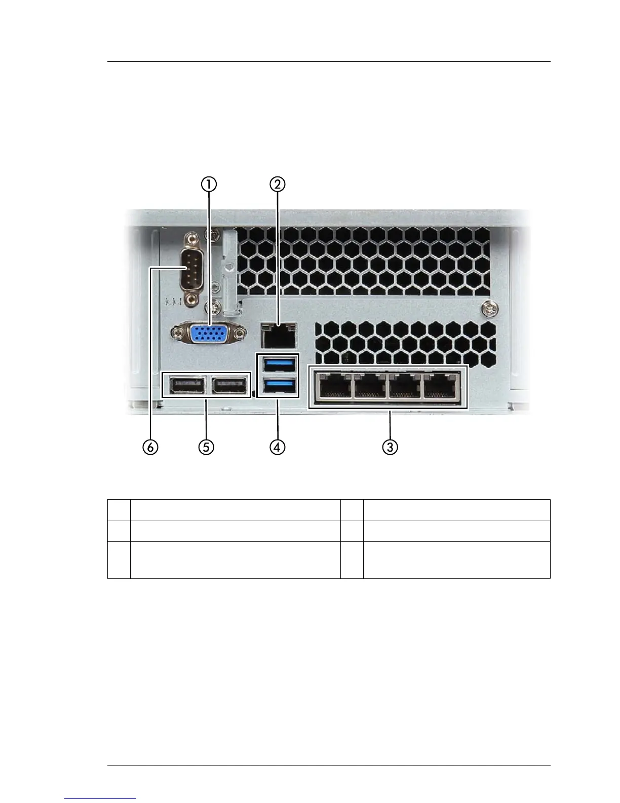
Figure 289: Connection panel on the rear
1 Video connector (blue) 4 2 USB connectors (USB 3.0)
2 Management LAN connector 5 2 USB connectors (USB 2.0)
3 Dynamic LoM (optional, different
variants)*.
6 COM1 connector (optional)**
* The LAN connectors on the dynamic LoM modules are numbered in
ascending order from right to left beginning with “0”. The rightmost
connector (LAN 0) is the shared LAN connector respectively.
** The serial interface COM1 can be used as the standard interface or for
communication with iRMC.

 Loading...


