Home
Fujitsu
Server
PRIMERGY TX2550 M5
Upgrade And Maintenance Manual
Page 85 (Installing the Riser Card)
Fujitsu PRIMERGY TX2550 M5 - Installing the Riser Card
636 pages
Manual
To Next Page
To Next Page
To Previous Page
To Previous Page
Loading...
4.8.1.2
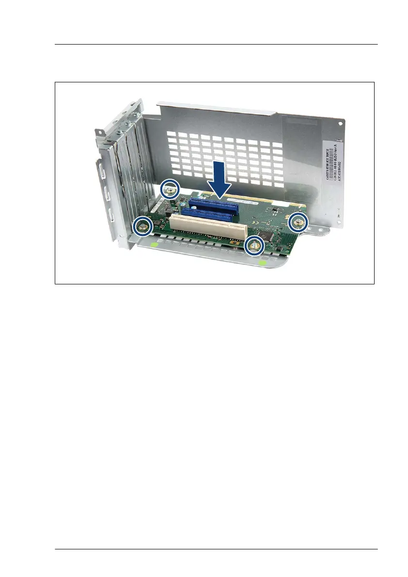
Installing the riser card
Figure 36: Installing the riser card
▶
Place the riser card on the riser card holder
.
▶
Fasten the riser card with four screws (see circles).
Basic hardware procedures
TX2550 M5
Upgrade and Maintenance Manual
85
84
86
Table of Contents
Main Page
Table of Contents
7
Notational Conventions
21
Introduction
21
Concept and Target Groups of this Manual
21
Before You Start
23
Basic Information
23
Proceeding
23
Advanced Thermal Design (ATD)
23
Installing Optional Components
24
Replacing a Defective Component
24
Customer Replaceable Units (CRU)
25
Assignment of Unit Categories
25
Classification of Procedures
25
Upgrade and Repair Units (URU)
26
Field Replaceable Units (FRU)
27
Average Task Duration
29
Tools You Need at Hand
30
Documentation Overview
30
About Availability of Manuals
30
List of Documents
30
Safety Instructions
33
Basic Safety Instructions
33
Introduction
33
Important Information
33
Before Starting up
34
Installation and Operation
34
Batteries
37
Working with Optical Disk Drives (Odds) and Media
37
Laser Information
39
Modules with Electrostatic-Sensitive Devices (ESD Modules)
39
Transporting the Server
41
Installing the Server in the Rack
42
Other Important Information
42
CE Conformity
43
Energy Star
43
FCC Class a Compliance Statement
44
Environmental Protection
45
Basic Hardware Procedures
47
Using Diagnostic Information
47
Proceeding
47
Locating the Defective Server
47
Determining the Error Class
48
Locating the Defective Component
48
Shutting down the Server
49
Disconnecting the Power Cord
50
Disconnecting the Power Cord (AC PSU)
50
Getting Access to the Component
51
Safety Notes
51
Rack Model
52
Extending the Server out of the Rack
52
Removing the Server from the Rack
53
Removing the Top Cover
55
Removing the Rack Front Cover
56
Floorstand Model
61
Unlocking the Server
61
Removing the Side Cover
62
Removing the Accessible Drive Bay Cover
63
Removing the Front Cover
64
Removing the HDD Bay Cover
64
Removing the System Air Duct
67
Reassembling
68
Safety Notes
68
Installing the System Air Duct
68
Rack Model
69
Installing the Rack Front Cover
69
Installing the Top Cover
70
Installing the Server in the Rack
72
Sliding the Server into the Rack
74
Floorstand Model
75
Installing the Front Cover
75
Installing the HDD Bay Cover
77
Installing the Accessible Drive Bay Cover
78
Installing the Side Cover
78
Locking the Server
80
Connecting the Power Cord
82
Connecting the Power Cord (AC PSU)
82
Switching on the Server
83
Handling Riser Modules
84
Riser Cards
84
Removing the Riser Card
84
Installing the Riser Card
85
Removing the Riser Module
86
Riser Modules
86
Installing the Riser Module
87
Handling the PCI Air Duct
88
Removing the PCI Air Duct
88
Installing the PCI Air Duct
89
Handling the Crossbar
90
Removing the Crossbar
90
Installing the Crossbar
91
Handling the Fan Bridge
92
Removing the Fan Bridge with Fan Modules (High Performance Variant)
92
Installing the Fan Bridge with Fan Modules (High Performance Variant)
93
Removing the Fan Bridge (Low Performance Variant)
94
Installing the Fan Bridge (Low Performance Variant)
95
Handling Accessible Drive Bays
96
Opening the Accessible Drive Locking Bar
96
Closing the Accessible Drive Locking Bar
98
Removing Accessible Drive Filler Covers
100
Installing Accessible Drive Filler Covers
101
Removing Accessible Drive Covers
101
Installing Accessible Drive Covers
102
Handling the Anti-Tilt Bracket
104
Removing the Anti-Tilt Bracket
105
Suspending Bitlocker Functionality
107
Validation
107
Starting the Maintenance Task
107
Basic Software Procedures
107
Disabling the Boot Watchdog
108
Removing Backup and Optical Disk Media
110
Verifying and Configuring the Backup Software Solution
110
Switching on the ID Indicator
110
Completing the Maintenance Task
111
Updating or Recovering the BIOS and Irmc S5
111
Verifying System Information Backup or Restore
114
Updating Expansion Card Firmware
115
Enabling Option ROM Scan
116
Reconfiguring the Backup Software Solution
117
Resetting the Boot Retry Counter
118
Resetting the Error Status after Replacing Memory Modules or Cpus
120
Resetting the Error Status after Replacing Memory Modules
120
Resetting the Error Status after Replacing Cpus
121
Enabling the Boot Watchdog
123
Enabling Replaced Components in the BIOS
124
Verifying the Memory Mode
125
Verifying the System Time Settings
126
Viewing and Clearing the System Event Log (SEL)
127
Updating the NIC Configuration File in a Linux and Vmware Environment
129
Resuming Bitlocker Functionality
130
Performing a RAID Array Rebuild
131
Looking for MAC/WWN/GUID and SAS Addresses
132
Basic Information
132
Looking for the MAC Address of a LAN Controller
132
Looking for the WWN Address of a Fibre Channel Controller
134
Looking for the GUID Address of an Infiniband or Omni-Path Controller
134
Looking for SAS Addresses of SAS Controllers for External Devices
135
Using the Chassis ID Prom Tool
136
Configuring LAN Teaming
138
Switching off the ID Indicator
139
Performing a Fan Test
140
Specifying the Chassis Model
141
Power Supply Unit (PSU)
143
Safety Notes
143
Basic Information
143
Redundant Power Supply
145
Installing a Hot-Plug PSU
145
Removing a Hot-Plug PSU
148
Replacing a Hot-Plug PSU
153
Power Distribution Board
155
Installing the Power Distribution Board
155
Removing the Power Distribution Board
158
Replacing the Power Distribution Board
161
Hard Disk Drive (HDD) / Solid State Disk (SSD)
163
Safety Notes
163
Basic Information
164
Handling Hdds or Ssds Without Installation Frame
166
Inch HDD/SSD and 2.5-Inch Installation Frame
166
Inch HDD/SSD and 3.5-Inch Installation Frame
168
Inch HDD and 3.5-Inch Installation Frame
170
Inch HDD Configurations
172
Equipping the 3.5-Inch HDD Bays
172
Overview Backplanes
172
Configuration with up to Four HDD Modules
173
Overview of Configurations
173
Configuration with up to Eight HDD Modules
174
Configuration with up to 12 HDD Modules
175
Installing 3.5-Inch HDD Modules
177
Removing 3.5-Inch HDD Modules
179
Replacing a 3.5-Inch HDD Module
182
Replacing a 3.5-Inch HDD SAS Backplane
183
Upgrading to 8X 3.5-Inch HDD Configurations
195
Inch HDD/SSD Configurations
202
Overview Backplanes
202
Configurations with up to Eight Hdds/Ssds
208
Overview of Configurations
208
Configurations with up to 16 Hdds/Ssds
209
Configuration with up to 24 Hdds/Ssds with HDD Extension Box
211
Configuration with up to 32 Hdds/Ssds with HDD Extension Box
213
Configurations with Additional Pcie-Ssds
215
Installing 2.5-Inch HDD/SSD Modules
218
Removing 2.5-Inch HDD/SSD Modules
220
Replacing a 2.5-Inch HDD/SSD Module
223
Installing 2.5-Inch Pcie SSD Modules
225
Removing 2.5-Inch Pcie SSD Modules
228
Replacing 2.5-Inch Pcie SSD Modules
230
Replacing a 2.5-Inch HDD SAS Backplane
231
HDD/SSD Modules)
258
Replacing the SAS Expander Board
258
Upgrading from 8X to 16X 2.5-Inch HDD/SSD Configurations
261
HDD Extension Box
265
Overview HDD/SSD Extension Boxes
265
Installing a 8X 2.5-Inch HDD/SSD Extension Box
266
Removing the 8X 2.5-Inch HDD/SSD Extension Box
271
Replacing the HDD/SSD Backplane on the 8X 3.5-Inch HDD/SSD Extension Box
274
Installing the 4X 3.5-Inch HDD Extension Box
277
Removing the 4X 3.5-Inch HDD Extension Box
281
Replacing the HDD Backplane on the 4X 3.5-Inch HDD Extension Box
283
Adding 2.5-Inch Pcie SSD Configurations
290
2.5-Inch Pcie SSD
290
Replacing the Pcie SSD Backplane on the 8X 2.5-Inch Pcie SSD Extension Box
294
Non Hot-Plug 2.5-Inch HDD/SSD
298
Replacing a Non-Hot-Plug 2.5-Inch HDD/SSD
298
Upgrading with Non-Hot-Plug Hdds/Ssds
304
SAS Expander Board
306
Installing the SAS Expander Board
306
Removing the SAS Expander Board
311
Replacing the SAS Expander Board
313
Fans
315
Safety Notes
315
Basic Information
315
Replacing a Fan Module (High Performance Variant)
316
Replacing a Fan Module (Low Performance Variant)
319
Replacing the Fan Bridge (High Performance Variant)
319
Replacing the Fan Bridge (Low Performance Variant)
320
Expansion Cards and Backup Units
323
Safety Notes
323
Basic Information
324
Handling Slot Brackets
327
Installing Slot Brackets
327
Removing Slot Brackets
329
Handling SFP+ Transceiver Modules
330
Installing SFP+ Transceiver Modules
330
Removing SFP+ Transceiver Modules
335
OCP (Open Compute Project) Modules
338
Installing an OCP Module
338
Removing an OCP Module
342
Replacing the OCP Module
345
Expansion Cards
346
Installing an Expansion Card
346
Removing an Expansion Card
358
Replacing an Expansion Card
361
Expansion Cards in Riser Modules
363
Installing an Expansion Card in a Riser Module
363
Removing an Expansion Card from a Riser Module
366
Replacing an Expansion Card in the Riser Module
369
Replacing a Riser Card
371
Installing a TFM
372
Removing a TFM
375
Replacing a TFM
378
Flash Backup Unit (FBU)
378
Variants of Fbus and FBU Cables
378
Installing an FBU
380
Removing an FBU
386
Replacing an FBU
390
Main Memory
393
Safety Notes
393
Slots and Features
394
Basic Information
394
General Memory Population Conditions
396
Modes of Operation
396
Ddr4 DIMM
396
Nvm/Lrdimm
399
DDR4 DIMM and NVM/LRDIMM Population Rules
400
Installing Memory Modules
401
Removing Memory Modules
403
Replacing Memory Modules
405
Handling Memory Dummy Modules
406
Basic Information
409
Processor (CPU)
409
Safety Notes
409
Upgrading to 2 Cpus Configuration
412
Replacing a CPU or Heat Sink
420
Accessible Drives
429
Safety Notes
429
Basic Information
429
Installing Accessible Drives
432
Removing Accessible Drives
440
Replacing Accessible Drives
442
Installing the Ultraslim ODD in the 4X 3.5-Inch HDD Extension Box
444
Ultraslim ODD in 3.5-Inch HDD Extension Box
444
Removing the Ultraslim ODD from the 4X 3.5-Inch HDD Extension Box
450
Replacing the Ultraslim ODD in the 4X 3.5-Inch HDD Extension Box
453
Ultraslim ODD in an Ultraslim ODD Adapter
455
Installing the Ultraslim ODD in the Ultraslim ODD Adapter
455
Removing the Ultraslim ODD from the Ultraslim ODD Adapter
459
Replacing the Ultraslim ODD in the Ultraslim ODD Adapter
461
Front Panel
463
Safety Notes
463
Replacing the Front Panel Module
463
Basic Information
473
Safety Notes
473
System Board and Components
473
CMOS Battery
474
Replacing the CMOS Battery
474
Trusted Platform Module (TPM)
476
TPM Kit
476
Installing the TPM
476
Removing the TPM
480
Replacing the TPM
485
Irmc Microsd Card
487
Note for Embedded Lifecycle Management (Elcm)
487
Installing the Irmc Microsd Card
487
Removing the Irmc Microsd Card
489
Replacing the Irmc Microsd Card
490
M.2 Ssd
491
Slots and Bolts for M.2 Ssds
491
Installing an M.2 SSD
492
Removing an M.2 SSD
496
Replacing the M.2 SSD
498
Dual Microsd 64GB Enterprise
500
Position of the Dual Microsd 64GB Enterprise
500
Installing the Dual Microsd 64GB Enterprise
500
Removing the Dual Microsd 64GB Enterprise
505
Replacing the Dual Microsd 64GB Enterprise
508
Replacing the Microsd Card
510
System Board
512
Replacing the System Board
512
Serial Interface
523
Safety Notes
523
Installing the Serial Interface
523
Removing the Serial Interface
526
Replacing the Serial Interface
527
Converting a Floorstand Model to a Rack Model
529
Cables
545
Replacing the Intrusion Switch Cable
545
Replacing the OOB Cable
554
Mechanical Overview
557
Server Front
557
Inch HDD/SSD Model
557
3.5-Inch HDD Model
558
Server Rear
561
Server with Air Cooling
561
Server Interior
562
Connectors and Indicators
564
System Board
564
Connectors and Indicators on the System Board
564
Indicators on the Front Panel
570
Server Front
570
Indicator on the ODD
573
Indicators on the Hot-Plug HDD/SSD Module
574
Server Rear
576
Connectors on the Server Rear
576
ID, CSS and Global Error Indicators
577
LAN Indicators
580
Indicator on Hot-Plug PSU
582
Acoustic Indicators
583
Onboard Settings
585
System Cabling Overview - English
591
List of Used Cables
592
List of Used Cables (Continuation)
593
Sysboardconn
594
Basic Frontpanel Intrusion
595
Basic Serial (RS-232)
596
Basic OOB 2X Bpl
597
Basic OOB 3X Bpl
598
Basic OOB 4X Bpl
599
Basic OOB Backplane Overview 24+8
600
Basic OOB 5X Bpl
601
Basic OOB 6X Bpl
602
Power PDB Red PSU
603
Power 2X 4X 3.5" + Acc Drv
604
Power 1X 8X 2.5" + Acc Drv
605
Power 3X 8X 2.5" + Acc Drv
606
Power 3X 4X 3.5" + Acc Drv
607
Power 24X 2.5"+ 8X 2.5" + Acc Drv
608
Power 2X 4X Pciessd
609
Power Ultraslimodd
610
Data 3X 4X 3.5" 1Con Exp
611
Data 3X 4X 3.5" + 2Xnhp 1Con Exp
612
Data 1X 8X 2.5" 1Con
613
Data 3X 8X 2.5" 1Con Exp
614
Data 24X 2.5" + 8X 2.5" 1Con Exp
615
Data 2X 8X 2.5" 1X Ep5X0I Nonexp
616
Data 2X 8X 2.5" 2Xcp/Ep4Xxi Nonexp
617
Data 2X 4X 3.5" 1Xep5X0I Nonexp
618
Data 1X 4X Pciessd Sl4 or Sl8 Retimer
619
Data 2X 4X Pciessd Sl8 and Sl9 Retimer
620
Data 2X 4X Pciessd 2Xep5X0I
621
Data Hddactivity Ep5X0I/E
622
Data LTO
623
Data ODD RDX
624
Data Dualmicro SD64GB Enterprise
625
Data APDUAL
626
Data RAID TFM FBU02
627
Data RAID TFM FBU345
628
Other manuals for Fujitsu PRIMERGY TX2550 M5
Operating Manual
106 pages
Related product manuals
Fujitsu PRIMERGY TX2550 M4
88 pages
Fujitsu PRIMERGY TX1320 M5
407 pages
Fujitsu PRIMERGY TX1310 M5
265 pages
Fujitsu PRIMERGY RX2540 M5
112 pages
Fujitsu PRIMERGY RX2520 M5
98 pages
Fujitsu PRIMERGY RX2530 M5
106 pages
Fujitsu PRIMERGY RX1330 M5
413 pages
Fujitsu PRIMERGY RX4770 M5
455 pages
Fujitsu PRIMERGY TX2540 M1
92 pages
Fujitsu PRIMERGY TX2560 M2
90 pages
Fujitsu PRIMERGY TX200 S2
317 pages
Fujitsu PRIMERGY TX200 S6
126 pages

 Loading...