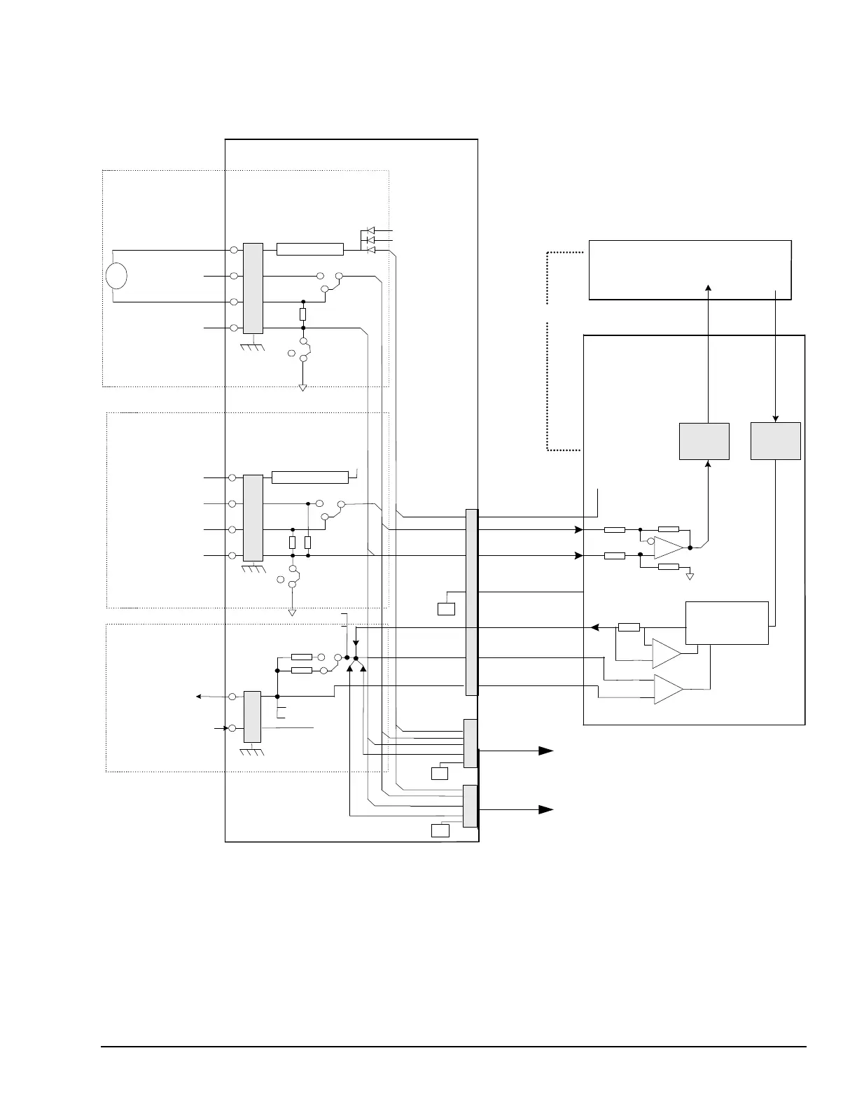
In a TMR system, analog inputs fan out to the three I/O packs. The 24 V dc power to the transducers also comes from all
three I/O packs and is diode shared on TBAI. Each analog current output is fed by currents from all three I/O packs. The
actual output current is measured with a series resistor, which feeds a voltage back to each I/O pack. The resulting output is
the voted middle value (median) of the three currents. The following figure displays TBAI in a TMR system.
Excitation
Current
Regulator /
Power Supply
A/D
D/A
Current Limit
JR1
Terminal Board TBAI
250
ohm
Open
1 ma
20 mA
JP#B
+24 V dc
+/- 1 mA
4- 20 mA
Return
Current Limit
Noise
Suppression
250 ohms
Open
Vdc
20 mA
JP#A
2 circuits per
terminal board
8 circuits per
Terminal board
5k ohms
JPO
Signal
Return
Two output circuits
#2 circuit is 4-20
mA only
JS1
JT1
200 mA
20 mA
S
T
S
T
P 28 V<S>
P 28 V<T>
P28VR
P28VR
JP#B
PCOM
Return
Return
SCOM
PCOM
JP#A
ID
ID
ID
+24 V dc
+/-5,10 V dc
4-20 mA
Return
T
SYSTEM
POWERED
N
S
N
S
N
S
<S> I/O Pack
<T> I/O Pack
Application Board
(internal to I/O pack
Processor Board
(internal to I/O pack
<R> I/O Pack
TMR Analog Inputs and Outputs
YAIC Analog I/O Modules GEH-6855_Vol_II System Guide 111
Public Information