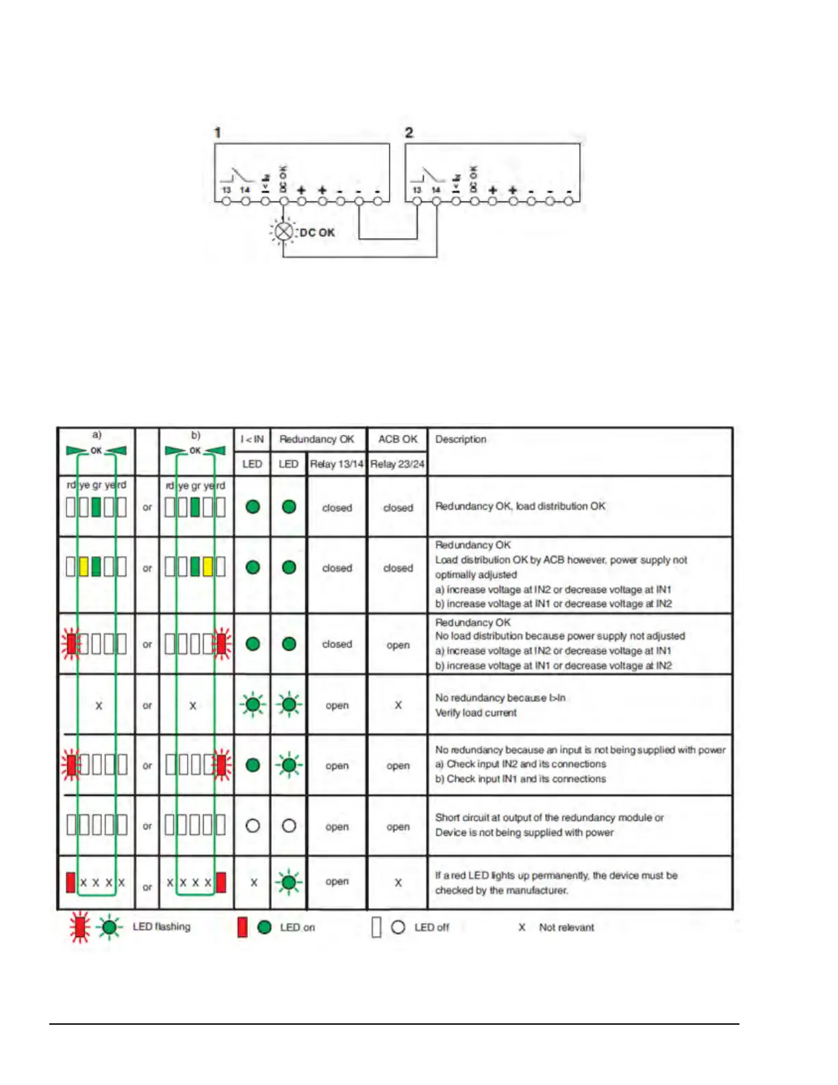
To create a signal loop, when monitoring two devices, use the active signal output of device 1 and loop in the floating signal
output of device 2. In the event of malfunction, a diagnostic alarm is generated. Any number of devices may be looped in.
This signal combination saves wiring costs and logic inputs.
Active Signal Loop
FET-OR Module Diagnostics
The Redundancy OK (13/14) and ACB OK floating (23/24) floating signal contacts monitor FET-OR module functionality as
defined in the following table. Additionally, the Redundancy OK LED, I < I
N LED, and the bar graph can be used to evaluate
redundancy module functionality on site. To monitor redundancy, the nominal current of the upstream power supply units can
be set on the module using the rotary selection switch.
FET-OR Module Diagnostic LED Indications
416 GEH-6855_Vol_II GEH-6855_Vol_II Mark VIeS Functional Safety Systems Volume II
Public Information


 To Next Page