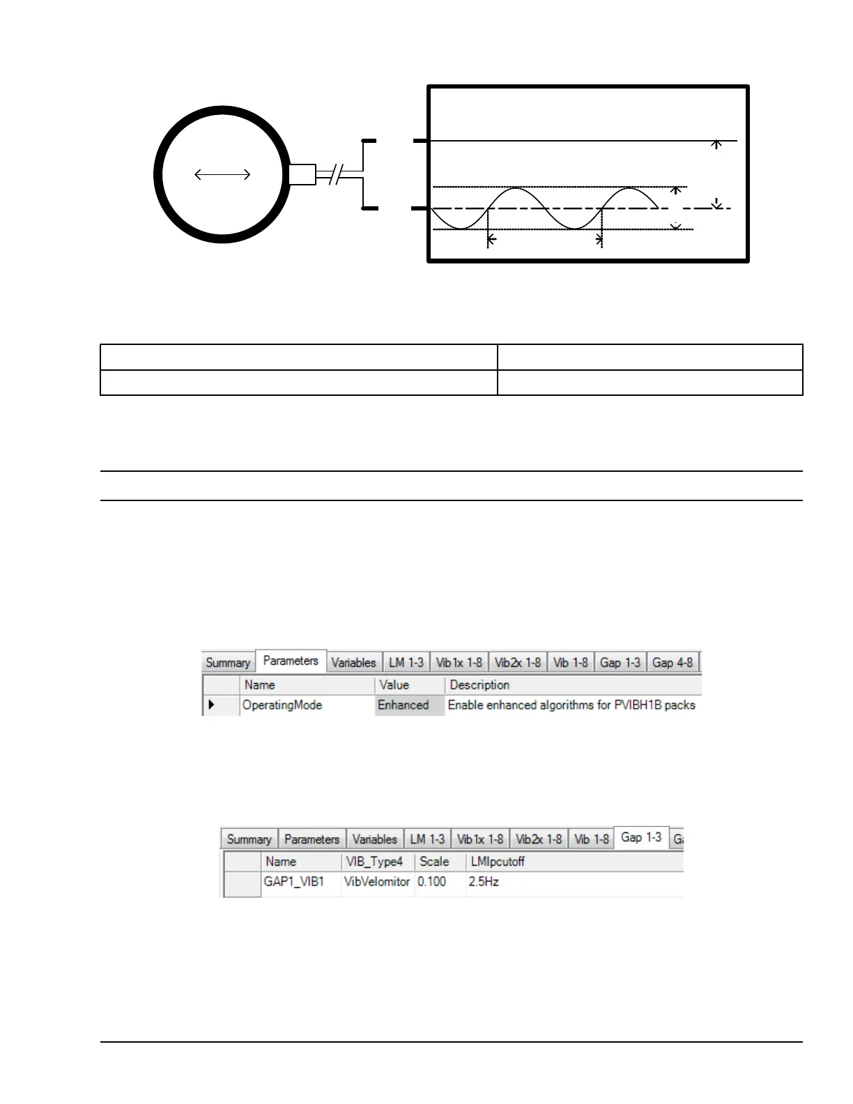
Velocity Application Example
PVIB/YVIB
N24V1
PR1H
1Vpp
(-12Vdc)
20ms (3000RPM)
In this example, Velomitor voltage inputs to a YVIB application are measured at the terminal board screws. Assume this
sensor is connected to Channel 1 as a VibVelomitor input.
Example Velomitor Specifications
Scale Factor 100mV/ips
Frequency Response 6 Hz to 750 Hz
We will configure Channel 1 for the following behaviors:
• Utilize the RMS Velocity algorithm for computing VIB1 signal.
Note Refer to Peak Velocity mode.
• Return VIB1 signal in inches/sec.
• Apply 8-pole low-pass and high-pass wideband filters to pass only inputs within Velomitor frequency response.
• Set SysLim1VIB1 to True if VIB1 ≥ 3 inches/sec
• Set SysLim2VIB1 to LATCH True if VIB1 ≥ 5 inches/sec
• Utilize LM_RPM_A to return LMVib1A as Peak Velocity at shaft speed (3000RPM) with a filter bandwidth of 5Hz.
Navigate to Parameters tab. Set OperatingMode parameter to Enhanced.
Navigate to “Gap 1-3” tab. Select GAP1_VIB1.
Set VIB_Type parameter to VibVelomitor.
Set Scale to “0.100” (Units are V/ips).
Set LMlpcutoff parameter to 2.5Hz. If the LM 1X Tracking Filter is not desired, then this setting does not matter.
Navigate to the Vib 1-8tab. Select VIB1.
Set VIB_CalcSel parameter to VIB_RMS.
Set FilterType to Bandpass. Set Filtrhpcutoff to “6.0” Hz.
Set Filtrlpcutoff to “750.0” Hz.
Set Fltrhpattn and Fltrlpattn to 8-pole.
YVIB Vibration Monitor Modules GEH-6855_Vol_II System Guide 255
Public Information