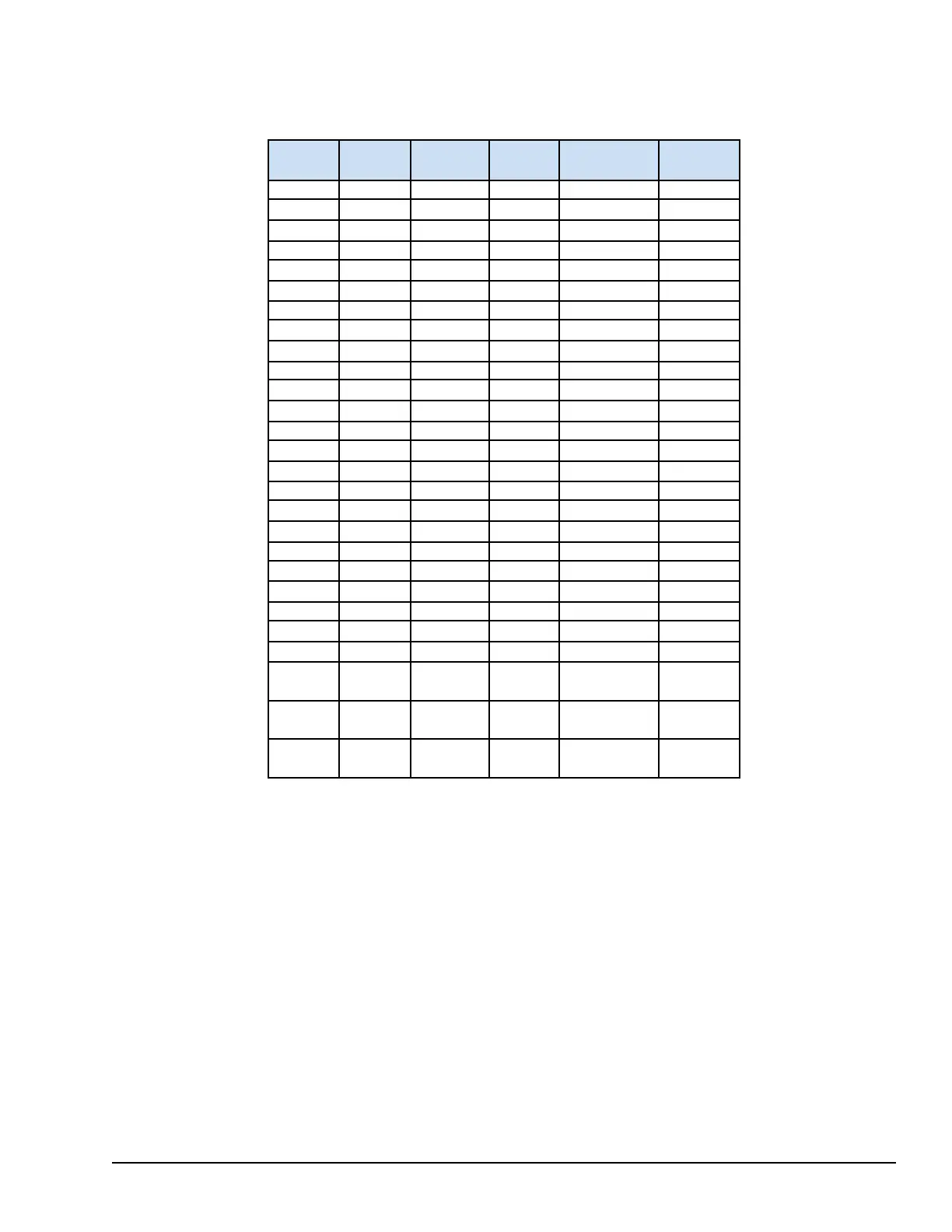
7.3.3.5 Wiring and Configuration for SRTD Retrofits
The following table provides a field wiring and channel comparison for retrofitting an existing SRTD with a SUAA terminal
board to provide RTD inputs.
SRTD
Screw
SRTD
Name
Channel
SUAA
screw
SUAA
Name
Use
1 EX01 1 5 IO- Excitation
2 SIG01 1 3 IO+
Signal
3 RET01 1 1
PWR_RET
Return
4 EX02 2 6 IO- Excitation
5 SIG02 2 4 IO+
Signal
6 RET02 2 2
PWR_RET
Return
7 EX03 3 11 IO- Excitation
8 SIG03 3 9 IO+
Signal
9 RET03 3 7
PWR_RET
Return
10 EX04 4 12 IO- Excitation
11 SIG04 4 10 IO+
Signal
12 RET04 4 8
PWR_RET
Return
13 EX05 5 17 IO- Excitation
14 SIG05 5 15 IO+
Signal
15 RET05 5 13
PWR_RET
Return
16 EX06 6 18 IO- Excitation
17 SIG06 6 16 IO+
Signal
18 RET06 6 14
PWR_RET
Return
19 EX07 7 23 IO- Excitation
20 SIG07 7 21 IO+
Signal
21 RET07 7 19
PWR_RET
Return
22 EX08 8 24 IO- Excitation
23 SIG08 8 22 IO+
Signal
24 RET08 8 20
PWR_RET
Return
25-34
No
connects
n/c
35
Chassis for
shields
Chassis
36
Chassis for
shields
Chassis
YUAA Universal I/O Modules GEH-6855_Vol_II System Guide 183
Public Information