6.1.3 YDOA Operation
The following features are common to the safety I/O modules:
• BPPx Processor Board
• Processor LEDs
• I/O Module Common Diagnostic Alarms
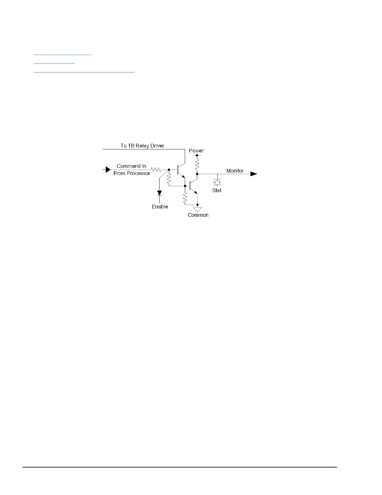
6.1.3.1 Relay Command Signals
The YDOA relay command signals are the first stage of signal conditioning and level shifting to interface the terminal board
outputs to the control logic. Each output is an open collector transistor circuit with a current monitor to sense when the output
is picked up and connected to a load. The status LEDs and monitor outputs indicate when an output is picked up and
connected to the terminal board. If an output is picked up and the correct load is not sensed, the status LED will be off and the
monitor line will be false.
6.1.3.2 Output Enable
All of the outputs are disabled during power application until a variety of internal self-tests is completed. An enable line
reflects the status of all required conditions for operation. This function provides a path independent of the command to
ensure relays stay dropped-out during power-up and initialization.
6.1.3.3 Monitor Inputs/Control
There are 15 inverting level shifting monitor input circuits. On a typical TRLY terminal board, 12 of these circuits are used as
relay contact feedbacks and the other three are used for fuse status. An inverting level shifting line is also provided from the
control to the terminal board for status feedback multiplexing control allowing the pack to receive two sets of 15 signals from
a terminal board.
134 GEH-6855_Vol_II GEH-6855_Vol_II Mark VIeS Functional Safety Systems Volume II
Public Information