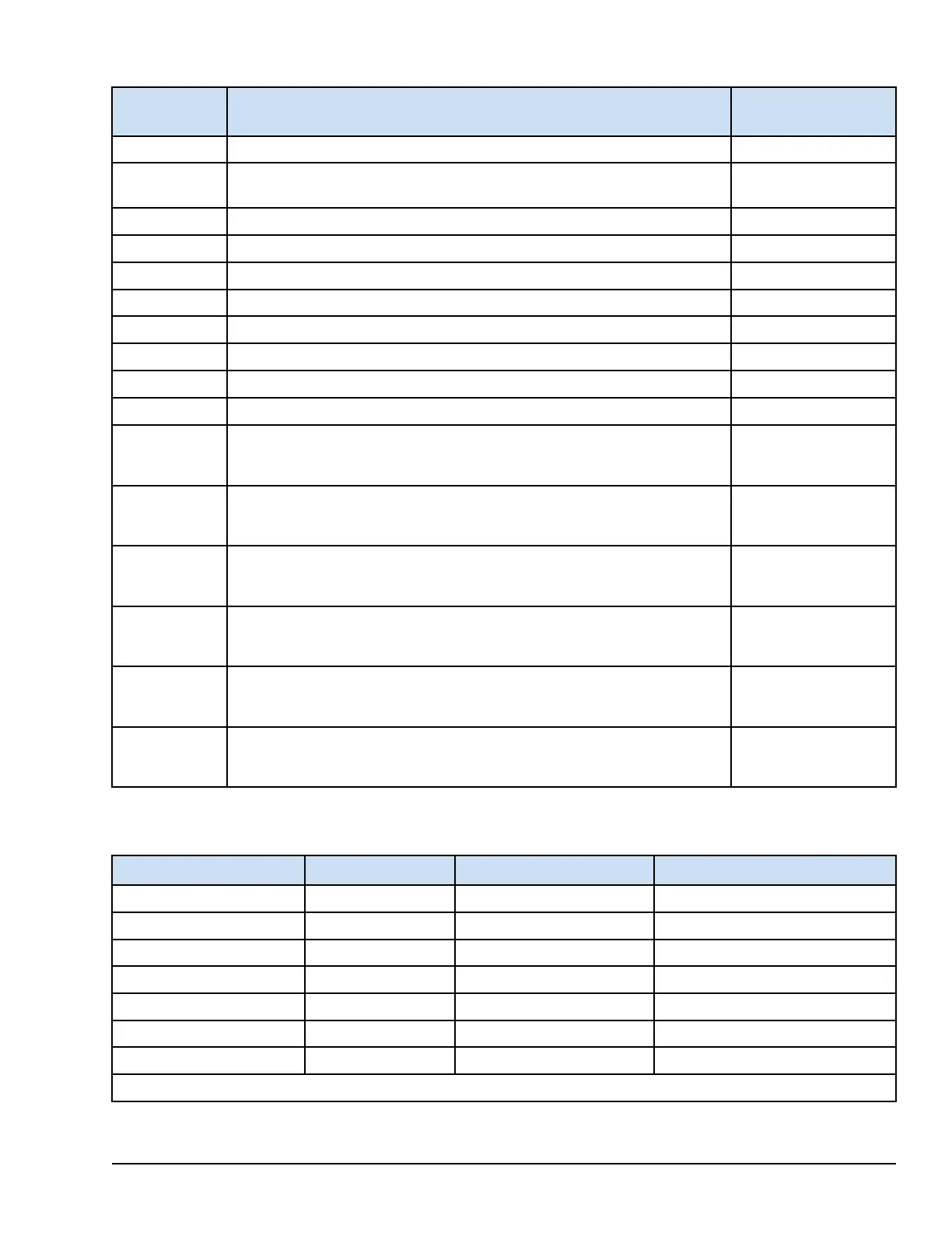
8.3.4.2 Variables
Variables Description
Direction and
Datatype
L3DIAG_YVIB_x I/O Pack Diagnostic Indicator where R, S, or T is the redundancy of pack Input BOOL
LINK_OK_YVIB_
x
IONet Link Okay Indicator where R, S, or T is the redundancy Input BOOL
ATTN_YVIB_x I/O Pack Status Indicator where R, S, or T is the redundancy Input BOOL
PS18V_YVIB_x I/O Pack 18 V Power Supply Indication where R, S, or T is the redundancy Input BOOL
PS28V_YVIB_x I/O Pack 28 V Power Supply Indication where R, S, or T is the redundancy Input BOOL
IOPackTmpr_ I/O Pack Temperature at the processor where R, S, or T is the redundancy Input BOOL
RPM_KPH1 Speed (RPM)of KP#1,calculated from input#13 Analog Input REAL
LM_RPM_A Speed A(RPM), calculated externally to the I/O Pack Analog Output REAL
LM_RPM_B Speed B(RPM), calculated externally to the I/O Pack Analog Output REAL
LM_RPM_C Speed C(RPM), calculated externally to the I/O Pack Analog Output REAL
SysLim1GAPx
where x = 1 to 13
Boolean set TRUE if System Limit 1 exceeded for Gap x input Input BOOL
SysLim2GAPx
where x = 1 to 13
Boolean set TRUE if System Limit 2 exceeded for Gap x input Input BOOL
SysLim1VIBx
where x = 1 to 8
Boolean set TRUE if System Limit 1 exceeded for Vib x input Input BOOL
SysLim2VIBx
where x = 1 to 8
Boolean set TRUE if System Limit 2 exceeded for Vib x input Input BOOL
SysLim1ACCx
where x = 1 to 9
Boolean set TRUE if System Limit 1 exceeded for Accelerometer x input Input BOOL
SysLim2ACCx
where x = 1 to 9
Boolean set TRUE if System Limit 2 exceeded for Accelerometer x input Input BOOL
8.3.4.3 Probe Nominal Settings
Probe Type
Gain
†
Snsr_Offset (Vdc) Scale (typical value)
Proximity 1x 9 200 mv/mil
Seismic 4x 0 150 mv/ips
Velomitor 2x 12 100 mv/ips
Accelerometer 2x 10 150 mv/ips
Keyphasor 1x 9 200 mv/mil
Bently Nevada CDM 2x 10 170 mv/psi
PCB CDM 2x -12 170 mv/psi
†
These are the default settings used if GnBiasOvride=Disable.
YVIB Vibration Monitor Modules GEH-6855_Vol_II System Guide 263
Public Information