9.3.3 Operation
The SSCA includes six connection points for each of the six serial communication channels. The points include four signal
lines A-D, a signal return, and a shield common (SCOM).
Signal Assignments
Protocol A B
C
D
Cable Length
RS-422 TX+ TX- RX+ RX- Up to 305 m (1000 ft)
RS-485 TX/RX+ TX/RX- Jumper from A Jumper from B Up to 305 m (1000 ft)
RS-232C DTR/RTS TX CTS RX Up to 15 m (50 ft) or 2500 pF
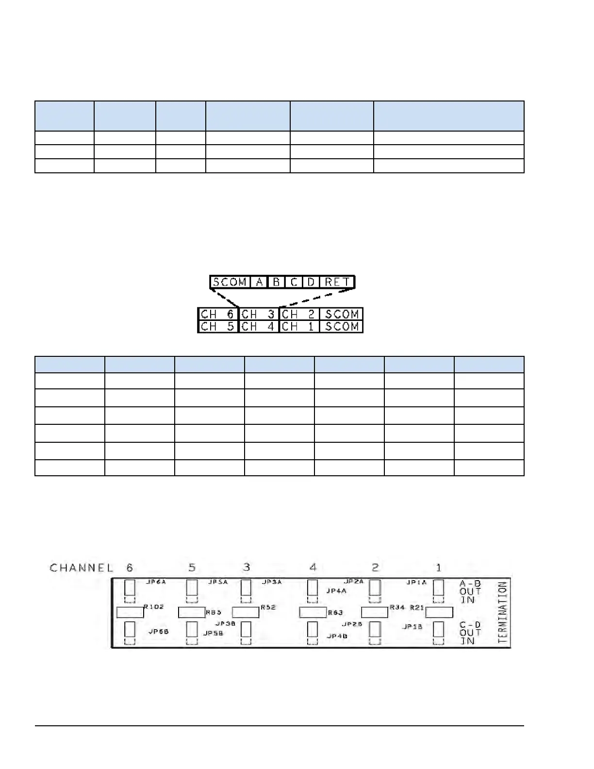
The return for RS-232C is through the terminal called Ret. The signals for all six serial communication channels are arranged
in the same order, which is SCOM, A, B, C, D, Ret when viewed from left to right.
The groups of six signals for a serial channel are assigned to terminals adjacent to each other. When viewed from left to right,
the channels on the bottom set of terminals are 5, 4, and 1. The top set of terminals contain channels 6, 3, and 2 when viewed
from left to right. The board SCOM connections are grouped on the right side of the terminals. A signal location diagram is
included on the SSCA.
Terminal Board Screw Connections
Connection
Port 1 Port 2 Port 3 Port 4 Port 5 Port 6
SCOM 26 25 13 14 2 1
PT_A 28 27 15 16 4 3
PT_B 30 29 17 18 6 5
PT_C 32 31 19 20 8 7
PT_D 34 33 21 22 10 9
Ret 36 35 23 24 12 11
When using RS-422 or RS-485, a termination resistor must be provided at either end of a transmission line. The SSCA
provides selectable termination resistors for each pair of signal lines. Jumpers JP1A and JP1B apply or remove the
termination resistors between signals A-B and C-D. The same function is repeated for each serial communication channel.
The default jumper position includes a disconnected termination resistor. The SSCA is clearly marked to display the
relationship of the termination jumpers and the serial communication channel signals as displayed in the following figure.
Termination Jumpers
294 GEH-6855_Vol_II GEH-6855_Vol_II Mark VIeS Functional Safety Systems Volume II
Public Information