Signal Name
Connector Pin #
PCOM JC1 6
BPR11 JC1 11
PCOM JC1 10
BPR12 JC1 23
PCOM JC1 24
BPR13 JD1 1
PCOM JD1 3
BPR14 JD1 5
PCOM JD1 9
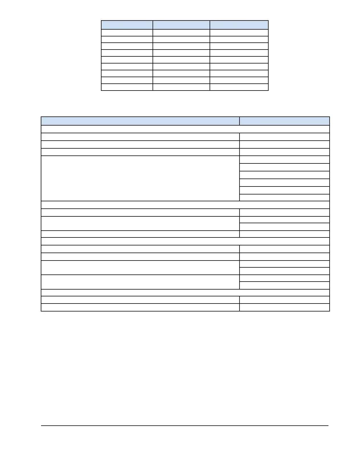
8.5.3 TVBA Specifications
Requirement
Limits
Input Options
Number of channels supporting position or gap inputs
13
Number of channels supporting velocity or dynamic pressure sensor inputs
8
Number of channels supporting Key Phasor inputs
2
Sensors Supported
1) Eddy-current or Proximitor
2) Accelerometer with integrated output
3) Seismic
4) Velomitor
5) Charge Amplifier
Sensor Power Options
Number of negative 24 V dc, N24 outputs to power sensors
14
N24 Nominal Voltage
-24.5 V dc
(-23 to -26) V dc
N24 maximum current 12 mA
Buffered Outputs
Number of buffered outputs
14
Buffer Gain Accuracy
+/-0.1%
DB9 and DB25 Connector Output Load requirements to achieve less than 10% overshoot
1500 ohms minimum
1000 pF maximum
BNC Connector Load requirements to achieve less than 10% overshoot
2 Mohm minimum
1000 pF maximum
Terminal Screws
Wiring Sizes
22 to 12 AWG
Torque 9.6 in-lb (1.085 N-m)
8.5.4 Diagnostics
The TVBA terminal board provides weak pull-up and pull-down circuits configured based on the jumper position to allow the
YVIB to detect an open circuit. The I/O pack creates the diagnostic alarm (fault) if any one of the inputs has an out-of-range
voltage.
Each connector between the TVBA and the I/O pack has its own ID device that is interrogated by the Vibration pack. The ID
device is a read-only chip coded with the terminal board serial number, board type, revision number, and the R, S and T
connector location. When this chip is read by the I/O pack and a mismatch is encountered, a hardware incompatibility fault is
created.
YVIB Vibration Monitor Modules GEH-6855_Vol_II System Guide 283
Public Information