10.10.3.6 Diagnostic LEDs
Power Supply Diagnostics
An active DC OK switching output signal, a floating DC OK signal contact, and an active POWER BOOST switching signal
output monitor power supply functionality as defined in the following table. Additionally, the DC OK LED and the Boost
LED can be used to evaluate power supply functionality directly at the installation site.
Power Supply Diagnostic LED Indications
Signal/LED
I < I
N I > IN UOUT < 0.9 x UN
DC OK On On
Flashing
Boost Off On On
Active DC OK switching output
On On Off
Floating DC OK output
Closed Closed
Open
Active POWER BOOST switching output
On Off Off
Indication
Normal operation of power
supply (U
OUT > 21.5 V)
POWER BOOST operation
(such as start loads)
Overload mode (such as
consumer short circuit or
overload)
When the floating DC OK output contact opens, the DC OK LED indicates that the set output voltage has fallen below 10%.
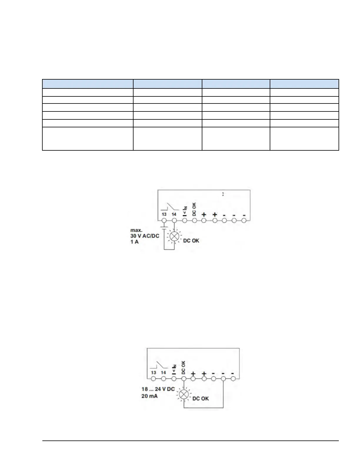
Signals and ohmic loads of up to 30 V max and currents of 1 A max (or 60 V max with 0.5 A max) can be switched. For
heavily inductive loads, such as a relay, a suitable protection circuit (such as a damping diode) is needed.
Floating DC OK Contact and DC OK LED Operation
The 18 – 24 V dc active signal output is applied between the DC OK signal and the negative (- ) connection terminal blocks
or between I < I
N and the negative (- ) connection terminal blocks, and can carry up to 20 mA. After switching from active
high to low, the DC OK LED indicates that the output voltage has fallen below 10%.
The DC OK output signal is decoupled from the power output to ensure that an external supply does not enter from devices
connected in parallel.
The POWER BOOST output signal I < I
N indicates that the nominal current has been exceeded, which places the power
supply unit in POWER BOOST mode. This monitors critical operational status to prevent a voltage dip. The 18 – 24 V dc
signal can be directly connected to a logic input for evaluation.
Active Signal Outputs and DC OK LED Operation
PDM Power Distribution Modules GEH-6855_Vol_II System Guide 415
Public Information