FET-OR Module Mounting and Installation
The FET-OR redundancy module can be snapped onto all DIN-rails according to EN 60715 (units are supplied with universal
snap-on foot for DIN-rails). The module should be mounted horizontally, connecting terminal blocks on top and bottom, with
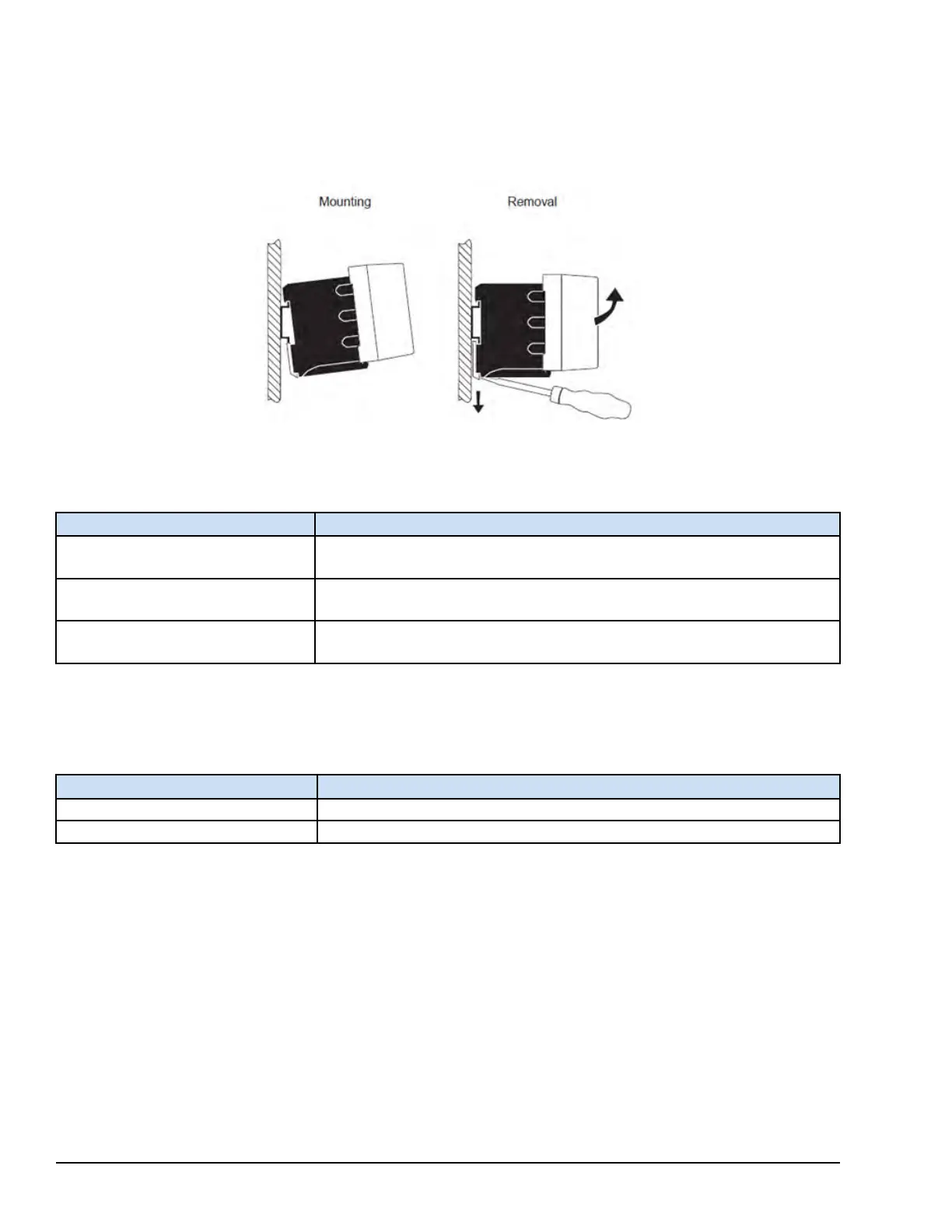
input terminal blocks facing upwards. The following figure displays the default mounting and removal position for the
redundancy module.
FET-OR Module Mounting and Removal Position
FET-OR Module Installation Depth
FET-OR Module
Mounting Position and Installation Depth
PF20A
Normal: 125 mm (4.92 in) (+ DIN-rail) (state at delivery)
Rotated with 270° Y-axis: 35 mm (1.38 in) (+ DIN-rail)
PF40A
Normal: 125 mm (4.92 in) (+ DIN-rail) (state at delivery)
Rotated with 270° Y-axis: 41 mm (1.61 in) (+ DIN-rail)
PF80A
Normal: 125 mm (4.92 in) (+ DIN-rail) (state at delivery)
Rotated with 270° Y-axis: 69 mm (2.71 in) (+ DIN-rail)
To ensure sufficient convection, adhere to the following guidelines for distance between the FET-OR module and other
modules.
FET-OR Module Convection Specifications
Mounting Position
Minimum Distance Between Modules
Vertical
50 mm (2.0 in)
Lateral
5 mm (0.20 in), 15 mm (0.60 in) between active components
406 GEH-6855_Vol_II GEH-6855_Vol_II Mark VIeS Functional Safety Systems Volume II
Public Information