Depending on the value of the VIB_CalcSel for each input, the filtered data will be used to provide Peak velocity within the
scan period, or RMS Velocity within the scan period.
For Peak velocity calculations, the wideband filter output is sent through a variable length peak detection function. The length
of the peak detection is determined by the Keyphasor 1 detected speed in RPM.
The output of the peak detection function (VPK) is passed through an adjustable 1-pole, low-pass filter prior to scaling. VPK
is converted from Volts to EU.
Wideband vibration information is passed through a variable scan period peak detection function. The length of the peak
detection is determined by the Keyphasor 1 detected speed in RPM.
Wideband Vibration Scan Period
Shaft speed (RPM) Scan period (ms)
0 – 60 160
60-480 2000
480-2250 250
>2250 160
Attention
Peak Detection functions and Capture Buffers always uses RPM_KPH1 speed.
The data in the buffer is used to compute an RMS voltage (V
RMS) over that capture length, which is passed through an
adjustable 1-pole, low-pass filter prior to scaling. V
RMS is converted from Volts to EU.
Note Sensors monitoring velocity typically measure RMS. Peak calculations can be used instead for legacy applications.
Note RMS calculations are only available with YVIBS1B systems, and can only be enabled by changing the OperatingMode
parameter to Enhanced.
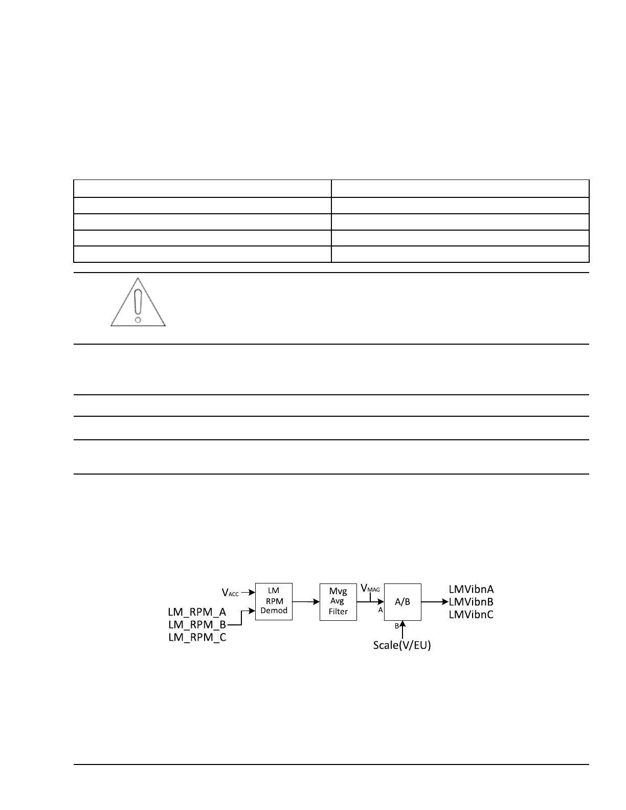
LMVibnA, LMVibnB, LMVibnC – Magnitude of 1X harmonic relative to specified rotor shaft in Engineering Units (EU).
This function is available for Inputs 1-3 only.
1X LM Tracking Filters measure the ½*pk-pk velocity component at a specified shaft speed in RPM. The YVIB module
receives the shaft speed through the variables LM_RPM_A (for LMVib1A, LMVib2A, and LMVib3A), LM_RPM_B (for
LMVib1B, LMVib2B, and LMVib3B), and LM_RPM_C (for LMVib1C, LMVib2C, and LMVib3C). The calculation is the
same for all 9 inputs, with only the input channel or shaft speed source changing. Values are converted from Volts to EU.
SysLim1GAPn, SysLim2GAPn – System Limit status for GAPn_VIBn value as True/False.
SysLim1VIBn, SysLim2VIBn – System Limit status for VIBn value as True/False. SysLim1ACCn, SysLim2ACCn – System
Limit status for LMVibnA/B/C value as True/False.
ACC1, ACC2, and ACC3 correspond to LMVib1A, LMVib1B, and LMVib1C.
ACC4, ACC5, and ACC6 correspond to LMVib2A, LMVib2B, and LMVib2C.
ACC7, ACC8, and ACC9 correspond to LMVib3A, LMVib3B, and LMVib3C.
YVIB Vibration Monitor Modules GEH-6855_Vol_II System Guide 253
Public Information