9.3 Triggering by Analog Signals
159
9
Chapter 9 Trigger Settings
Description About period range settings
The period range settings for period triggering depend on the sampling period
(sampling rate). (Changing the timebase also changes the period setting range.)
The sampling rate setting can be verified on the Status screen - Status sheet.
The upper threshold of the period range cannot be set below the lower threshold,
and vice-versa.
Lower threshold: can be set either to zero, or to at least five times the sampling
period.
Upper threshold: can be set to no more than 2,000 times the sampling period.
To apply a trigger when the frequency increases (shorter period) above the
upper threshold:
Set the period trigger type to [Per.I], and the lower threshold to [0]. The lower
threshold is ignored, and triggering occurs when the frequency exceeds that cor-
responding to the upper threshold.
To apply a trigger when the frequency decreases (longer period) below the upper
threshold:
Set the period trigger type to [Per.O], and the lower threshold to [0]. The lower
threshold is ignored, and triggering occurs when the frequency drops below that
corresponding to the upper threshold.
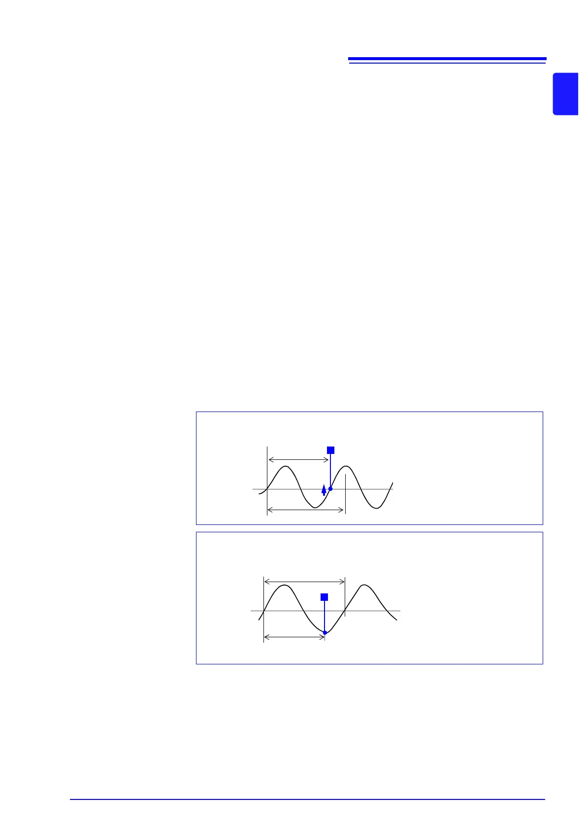
About the trigger point of the Out-of-Period trigger
Triggering occurs when the period of sequential crossings of the specified refer-
ence voltage exceeds the period range.
The point at which triggering occurs depends on the specified period range and
the period of the measured signal.
Reference
Voltage Level
Lower Threshold
Input Signal
Period
T
Triggering occurs when the rising
edge (↑ trigger slope) of the input
signal crosses the reference volt-
age level, before reaching the low-
er period threshold.
When the input signal period is shorter than the specified lower threshold
(Trigger Slope:
↑)
Reference
Voltage Level
Upper Threshold
Input Signal
Period
T
Triggering occurs when the upper
threshold period is reached, be-
fore the rising edge (↑ trigger
slope) of the input signal crosses
the reference voltage level.
Therefore, the trigger point is de-
termined by the upper threshold
of the period range.
When the input signal period is longer than the specified upper threshold
(Trigger Slope:
↑)


 To Next Page