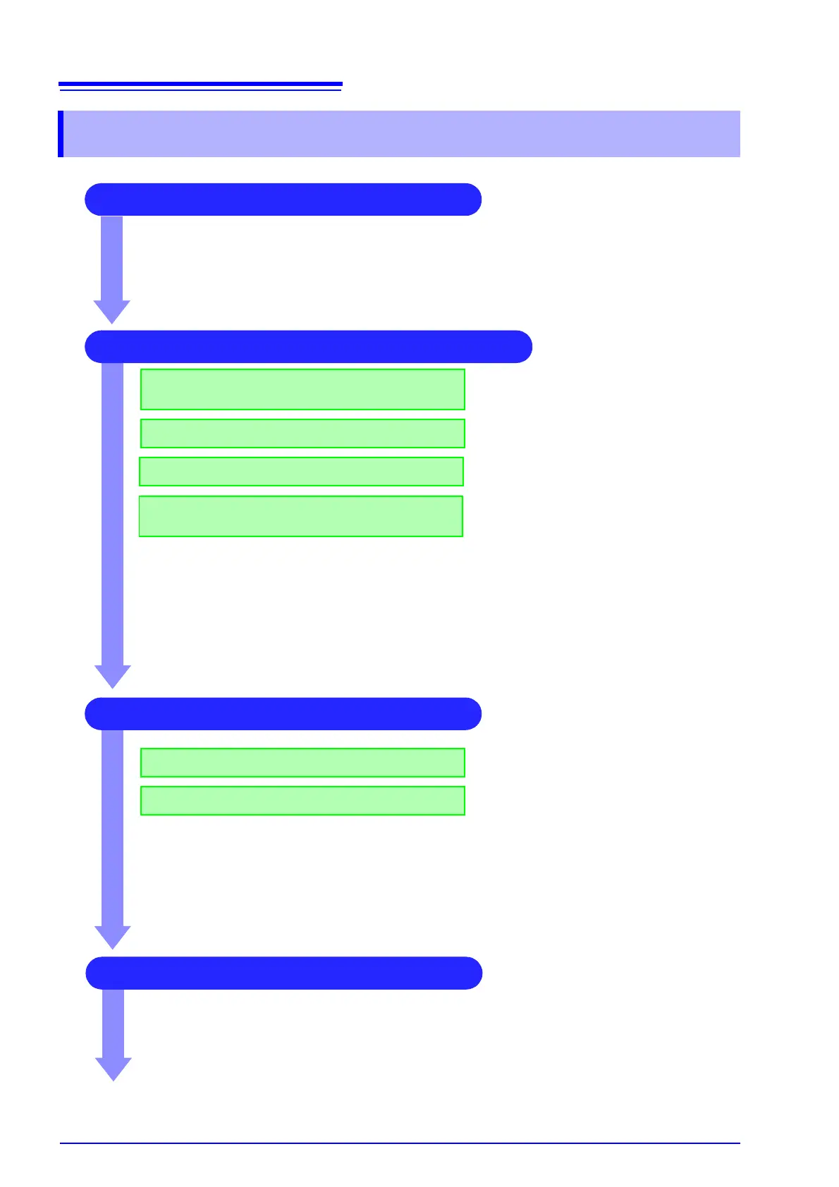
2 Make basic settings for measurement
Set waveform length
Select suitable recording method for
measurement target
Set data acquisition speed
Set waveform display format and printing
format
See:
"3.4.1 Measurement Function" (
p.41)
"3.4.2 Time Axis Range and Sampling Rate"
( p.43)
"3.4.3 Recording Length (number of divisions)"
( p.46)
"3.4.4 Screen Layout" (
p.48)
Application examples
See:
"7.4 Performing Waveform X-Y Synthesis" (
p.108)
"8.2 Displaying Waveforms During Recording (Roll Mode)" (
p.124)
"8.3 Displaying New Waveforms Over Past Waveforms (Overlay)" (
p.125)
"8.4 Setting Channels to Use (Extending the Recording Length)" (
p.127)
"Chapter 10 Numerical Calculation Functions" (
p.173)
3 Input Channel Settings
Make analog channel settings
Make logic channel settings
See:
"3.5.2 Analog Channel" (
p.52)
"3.5.3 Logic Channel" (
p.55)
Application examples
See:
"8.1 Adding Comments" (
p.118)
"8.5 Converting Input Values (Scaling Function)" (
p.128)
"8.6 Variable Function (Setting the Waveform Display Freely)" (
p.134)
"8.7 Fine Adjustment of Input Values (Vernier Function)" (
p.137)
4 Make trigger settings
See:
"Chapter 9 Trigger Settings" (
p.151)
1 Pre-Measurement Inspection
See:
"3.3 Pre-Measurement Inspection" (
p.40)