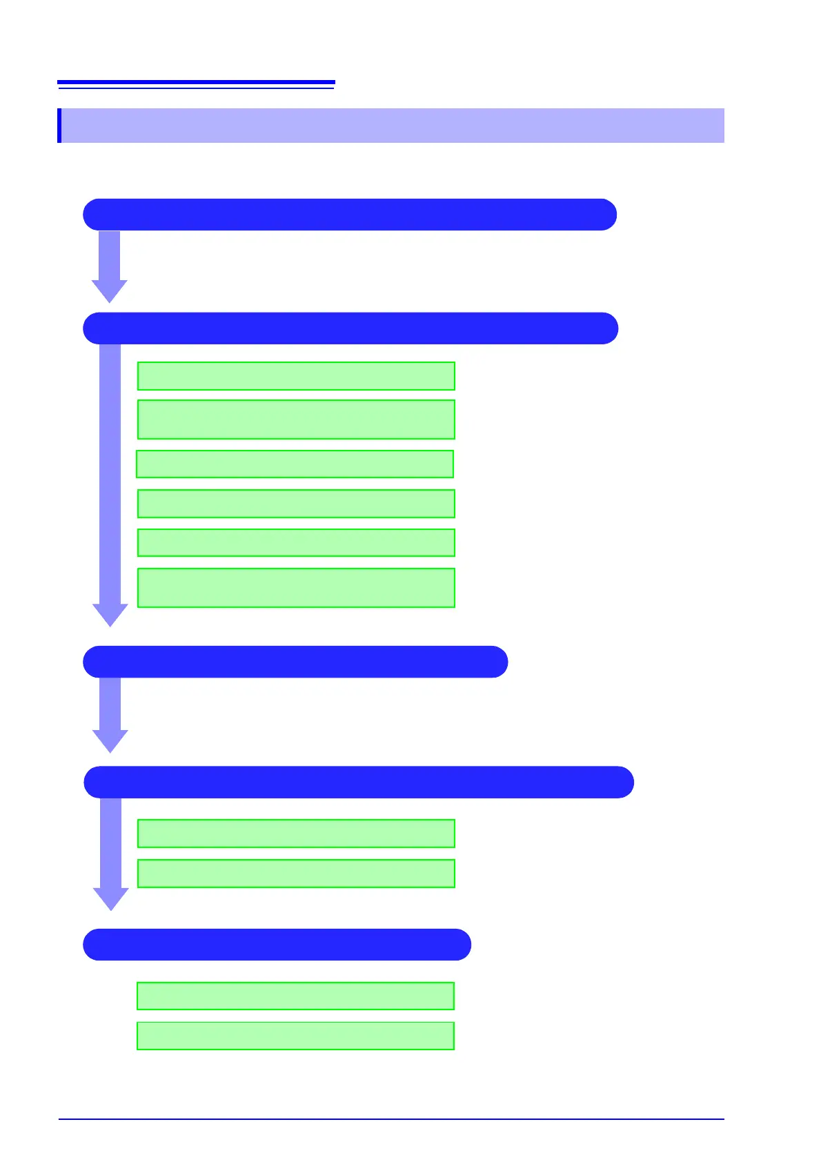
2 Make input and screen display related settings
Make filter settings (if noise occurs)
Select input coupling
Match range to measurement target input value
(as necessary)
See:
"3. Coupling" (
p.52)
"2. Vertical axis (Voltage axis) Range" (
p.52)
"8.5 Converting Input Values (Scaling Func-
tion)" ( p.128)
"7. Low-pass filtering" ( p.54)
3 Make trigger settings (as necessary)
4 Make display color and display position settings
See:
"Chapter 9 Trigger Settings" (
p.151)
1 Select the channels to use (Memory function) only)
See:
"8.4 Setting Channels to Use (Extending the Recording Length)" (
p.127)
Convert input value (as necessary)
Fine-tune waveform amplitude (as necessary)
Set zoom on vertical axis (voltage axis) direction
(as necessary)
"5. Vernier" ( p.53)
"4. Vertical axis (Voltage axis) Zoom" ( p.53)
Set waveform display color
Set display position and scaling (as necessary)
See:
"1. Waveform Display Color" (
p.52)
"8.6 Variable Function (Setting the Waveform
Display Freely)" (
p.134)
4 Make graph display settings
For 1, 2, 4, 8 screens
For X-Y1, X-Y4 screens
See:
"Analog Channel Assignment" (
p.48)
Procedures "4" and “5” of "7.4 Performing
Waveform X-Y Synthesis" (
p.109)