3.5 Input Channel Setting
54
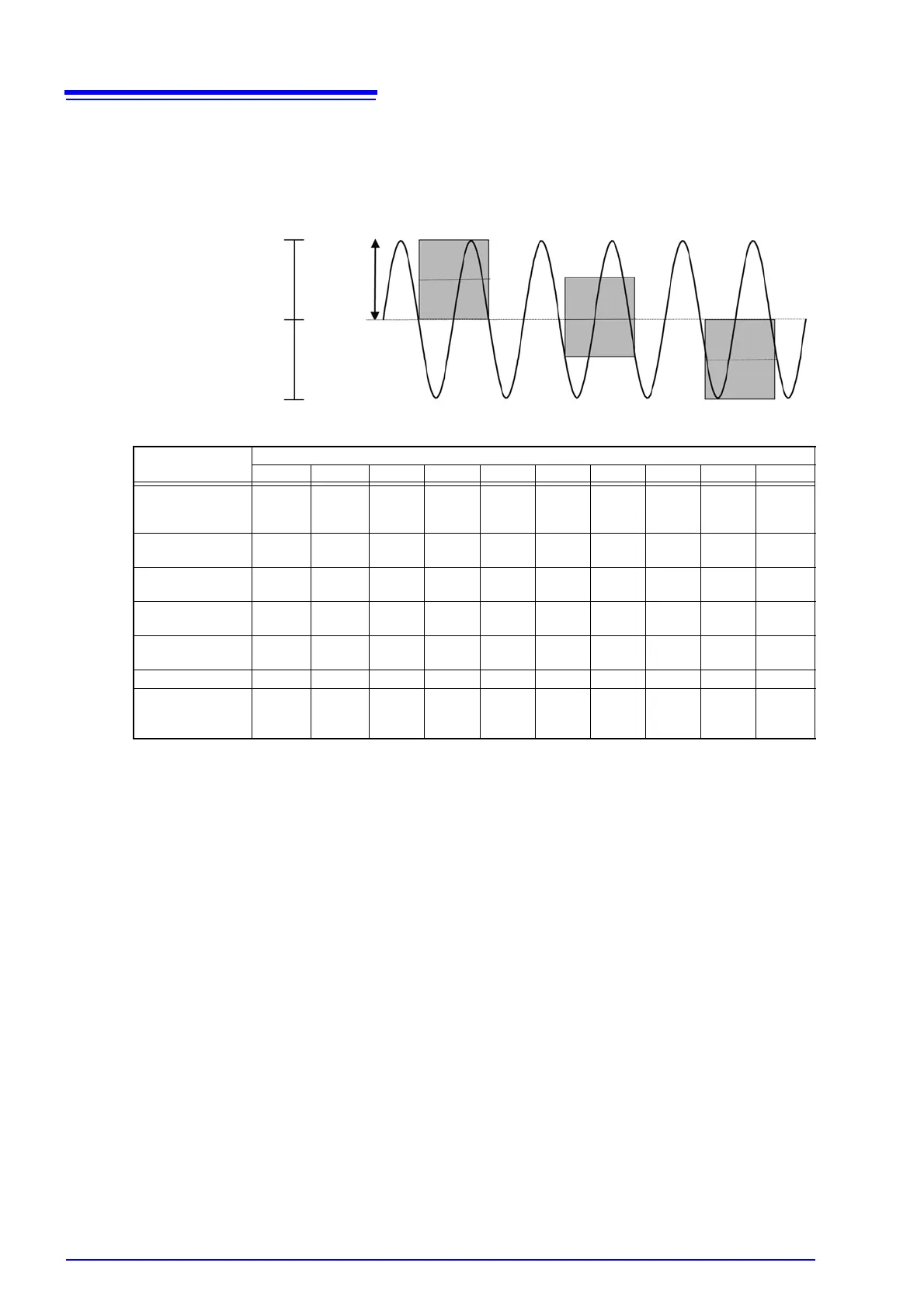
The zero position is as shown in the illustration below.
(Example: 8966 Analog Unit)
Brackets indicate valid data range
*: With the 8967 Temp Unit, the valid range differs depending on the thermocouple. For information on the minimum resolution,
see the specifications of the 8967 Temp Unit.
7. Low-pass
filtering
Make settings for the low-pass filter of the input module. This is useful for elimi-
nating unwanted high-frequency components. The filter type depends on the
module. Make the setting according to the input characteristics.
A/D Data
2047
0
-2047
A/D Data
0 V
2000 LSB
0 %
50 %
100 %
Display screen
(Zero position: 0%)
Display screen
(Zero position: 50%)
Display screen
(Zero position:100%)
<Zoom factor ×1>
Full-scale resolution for input units at various vertical axis zoom factors (LSB)
Input module Zoom factor
×1/10 ×1/5 ×1/2 ×1 ×2 ×5 ×10 ×20 ×50 ×100
8966 (Analog)
8971 (Current)
8972 (DC/RMS)
20000
(4000)
10000
(4000)
4000 2000 1000 400 200 100 40 20
8967
(Temperature)
*
200000 10000 40000 20000 10000 4000 2000 1000 400 200
8968
(High resolution)
320000
(64000)
160000
(64000)
64000 32000 16000 6400 3200 1600 640 320
8969 (Strain) 250000
(64000)
125000
(64000)
50000 25000 12500 5000 2500 1250 500 250
8970
(Power frequency )
20000 10000 4000 2000 1000 400 200 100 40 20
8970 (Count ) 400000 200000 80000 40000 20000 8000 4000 2000 800 400
8970 (Excluding
power frequency
and count)
100000 50000 20000 10000 5000 2000 1000 500 200 100