9.4 Triggering by Logic Signals (Logic Trigger)
160
The steps for making settings and selecting the type of logic trigger are described below.
The Trigger settings window ([Logic Trig] sheet) is used.
• Input signals on logic channels serve as the trigger source. Triggering occurs
when the specified trigger pattern and logical probe combining criteria (AND/
OR) are met.
• The trigger detection method can be selected according to whether a trigger is
applied or not when the criteria are already met at the start of measurement.
• By using the trigger filter, triggering can be limited so as to occur only when
trigger criteria are met for at least the specified filter width.
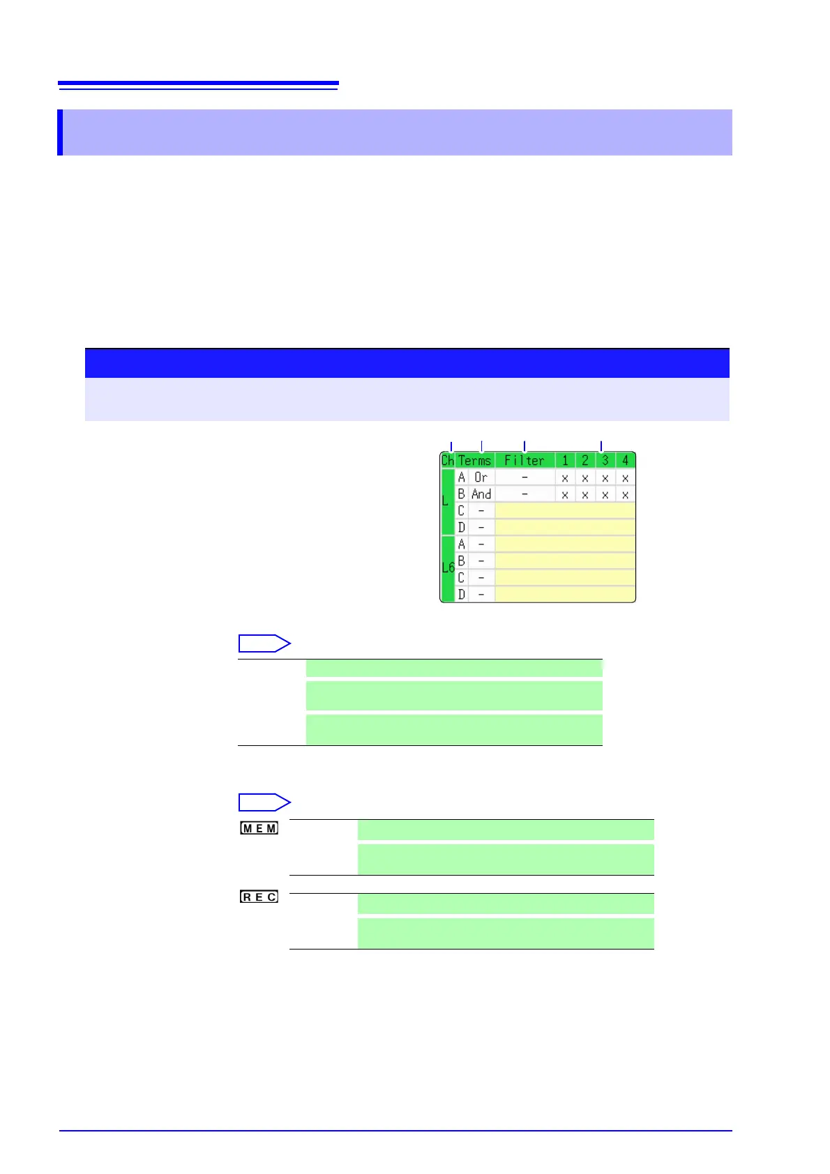
1. Trigger Sets the trigger probe combining logic (AND/OR).
2. Filter Sets the filter width (trigger filter) for triggering. (as occasion demands)
Suppresses triggering from noise.( p.158)
9.4 Triggering by Logic Signals (Logic Trigger)
Procedure
To open the screen: Press the DISP key → Waveform screen → Press the TRIG.SET key → Trigger settings
window ([Logic Trig] sheet)
1
Move the cursor to the channel you want to set.
2
Use the F keys to make the setting.
1. 2. 3.
Logic Channels
Off Logic triggering is disabled. (default setting)
OR
Triggering occurs when input signal logic matches any set-
ting in the trigger pattern.
AND
Triggering occurs only when input signal logic matches all
settings in the trigger pattern.
Off
Trigger filtering is disabled. (default setting)
0.1 to 10
Trigger filtering is enabled.
The filter width is set as a number of divisions.
Off
Trigger filtering is disabled. (default setting)
On
Trigger filtering is enabled. Filter width is 10 ms (or 5 ms
when the sampling rate is 100 ns/S)