16.2 External I/O
290
Signals can be output that indicate the instrument's judgment state.
1. Connect the GO/EXT.OUT1, NG/EXT.OUT2, and GND terminals to the device(s)
to be controlled by single wires.
See: "16.1 Connecting External Control Terminals" ( p.288)
2. Press the SYSTEM key to open the [Environment] sheet, and move the cursor
to [GO/EXT OUT1] or [NG/EXT OUT2].
3. Select the conditions under which the instrument outputs a signal.
(when the [GO/EXT OUT1] item is selected)
(when the [NG/EXT OUT2] item is selected)
4. The signal for the specified state is output.
16.2.2 External Output (GO/EXT.OUT1) (NG/EXT.OUT2)
Signal Output Procedure
Measure A LOW signal is output when the judgment result is GO (pass).
Error
Output a LOW level signal when an error occurs.
Busy
A LOW signal is output when external start operation is disabled, such as during
startup, saving, and printing.
Trigger
Output a LOW level signal while instrument is waiting for a trigger.
Measure
A LOW signal is output when the judgment result is NG (fail).
Error
Output a LOW level signal when an error occurs.
Busy
A LOW signal is output during measurement, saving, and printing, and when it’s
finished, a HIGH signal is output.
Trigger
Output a LOW level signal while instrument is waiting for a trigger.
Calibration
1 kHz output for calibrating Model 9665 10:1 Probe and the 9666 100:1 Probe.
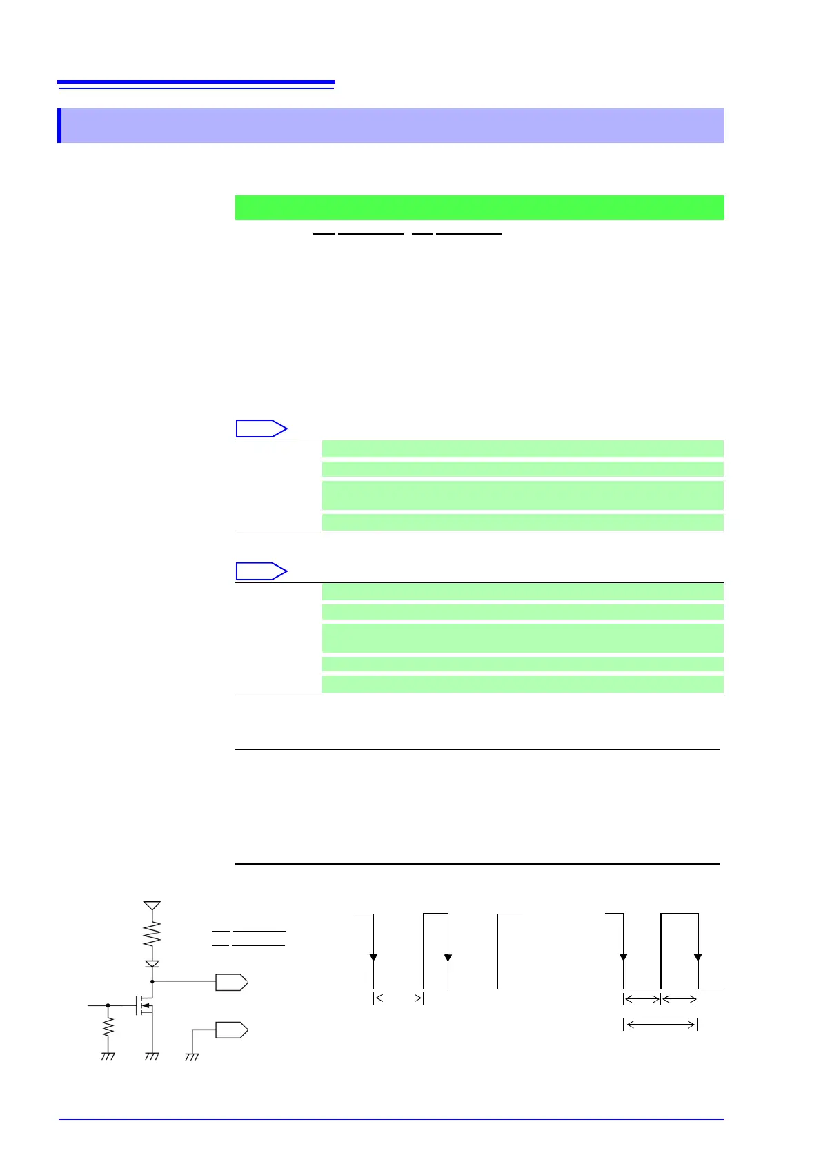
Output signal Open drain output (with voltage output) active LOW
Output voltage
range
HIGH level: 4.0 to 5.0 V, LOW level: 0 to 0.5 V
Maximum input
voltage
50 VDC, 50 mA, 200 mW
HIGH
4 to 5.0 V
LOW
0 to 0.5 V
Output period
HIGH
4 to 5.0 V
LOW
0 to 0.5 V
1 ms
500 μs 500 μs
Probe Calibration Active
Probe Calibration Inactive
GND
GO/EXT.OUT1
NG/EXT.OUT2
10 kΩ
10 kΩ
5 V