Connecting External I/O Terminals (Connector Blocks)
Cables to connect
Recommended cables:
single strand diameter: φ 1.0 mm (AWG18)
multi-strand: 0.75 mm
2
(AWG20)
Usable cables:
Single strand diameter: φ 0.4 - 1.0 mm (AWG26 to 18)
Multi-strand: 0.3 - 0.75 mm
2
(AWG22 - 20)
Strand diameter: φ 0.18 mm or greater (per wire)
Standard insulation stripping length: 10 mm
Button operation specified tool: Flat-blade screwdriver (tip width 2.6 mm)
Single strand
Multi-strand
10 mm
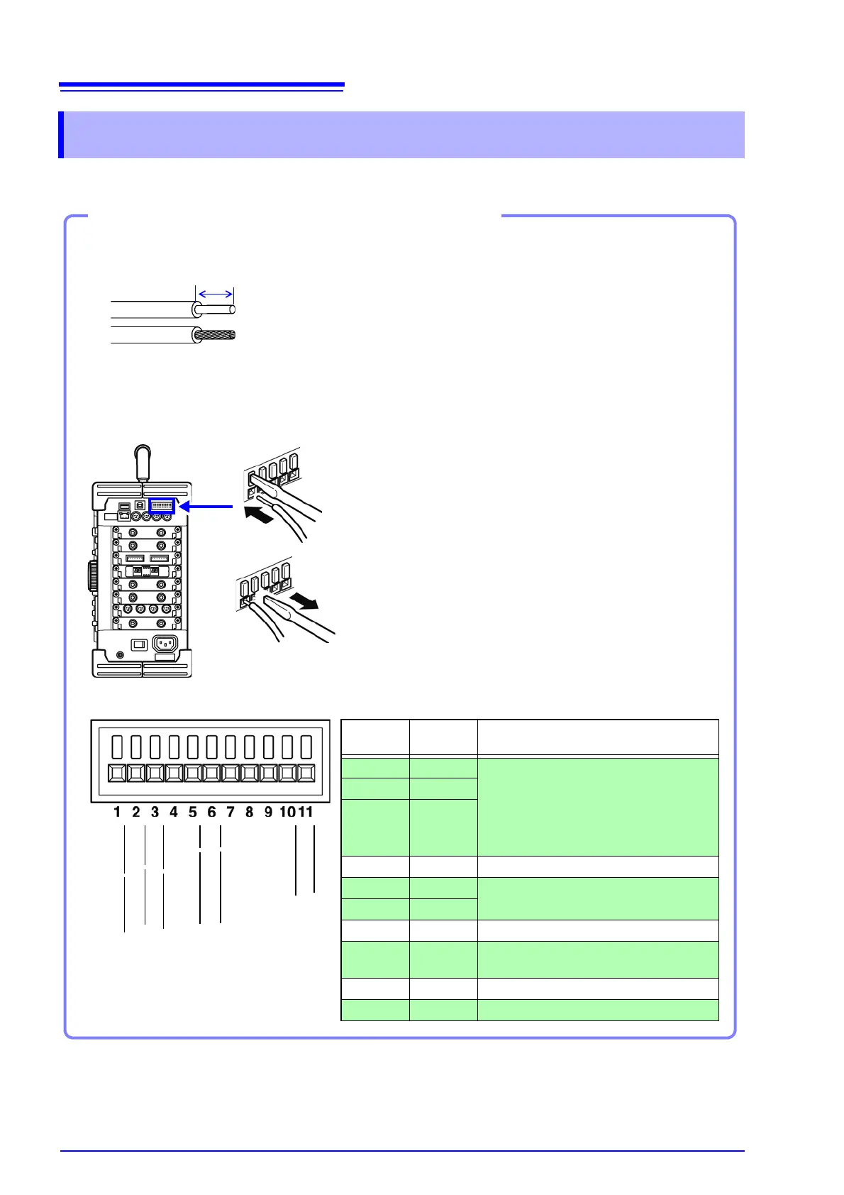
Connection procedure
1. Push in the button on the connector with a flat-
blade screwdriver or other tool.
2. With the button held in, insert the cable into the
cable connection hole.
3. Release the button.
The cable is locked.
1
2
3
EXT.TRIG
TRIG OUT
GND
EXT.SMPL
GND
NG
/EXT.OUT2
GO/EXT.OUT1
GND
STOP/EXT.IN2
START/EXT.IN1
PRINT/EXT.IN3
Terminal
No.
Terminal
Color
Operation
1 Blue Input external signal and execute the fol-
lowing
• Start/end measurement
• Print/save data
• Pen up/down (for X-Y recorder opera-
tion)
2 Purple
3 White
4Black -
5 Green
Output instrument status as a signal
6 Red
7Black -
8 Gray
Input external signal and set sampling
rate
9Black -
10 Yellow Output signal when triggering occurs